Performance and Variability-Driven Guidelines for BEOL Layout Decomposition in LELE Double Patterning
This paper explores the impact of stitching locations and strategies on the performance and variability of Double Patterning Lithography (DPL) for Back-End-Of-Line (BEOL) layout decomposition. By analyzing interconnect patterns, we derive analytical equations for RC variations using commercial and predictive technology parameters. Our results indicate that optimal stitching locations, particularly shifted toward the driver’s side, minimize timing variability and capacitance variations, with improvements observed in both 45nm and 22nm technologies, demonstrating the advantages of redundant stitching.

Performance and Variability-Driven Guidelines for BEOL Layout Decomposition in LELE Double Patterning
E N D
Presentation Transcript
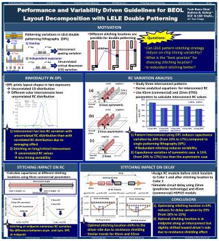
victim neighbors victim neighbors neighbor victim Performance and Variability Driven Guidelines for BEOL Layout Decomposition with LELE Double Patterning Color 1 Tuck-Boon Chan† Andrew B. Kahng†‡ ECE† & CSE‡ Depts., UC San Diego SR SL SL SR W2 Color 2 SL W1 T X Cc Cs Cs Cs Cc Cc H Ground plane Ground plane Ground plane Y MOTIVATION Patterning variations in LELE double patterning lithography (DPL) • Different stitching locations are • possible for double patterning Resist Hardmask Questions: Metal 1st Exp. & Etch • Can LELE pattern stitching strategy reduce on-chip timing variability? • What is the “best-practice” for choosing stitching location? • Is redundant stitching better? 1) Overlay 2) Independent exposures Interconnect spacing variation 1stExp. 2ndExp. stitches 2nd Exp. Uncorrelated critical dimension (CD) variation 1stExp. 2ndExp. 2nd Etch Final patterns BIMODALITY IN DPL RC VARIATION ANALYSIS • Study three interconnect patterns • Derive analytical equations for interconnect RC • Use 45nm (commercial) and 22nm (ITRS) parameters to calculate interconnect RC values • DPL prints layout shapes in two exposures Uncorrelated CD distribution Different-color interconnects have uncorrelated RC distribution (a) 3 lines symmetric (b) Capacitance variation3/ (%) 1) Interconnect has less RC variation with uncorrelated RC distribution than with correlated RC distribution due to averaging effect 2) Stitching on long/critical interconnect uncorrelated RC values less timing variability 3 lines asymmetric 1) Pattern interconnect using DPL reduces capacitance variation by 20% (from 23% to 17%) compared to single patterning lithography (SPL)Redundant stitching reduces variability 2) Capacitance variation of symmetric case is 15% (from 20% to 17%) less than the asymmetric case (c) 2 lines STITCHING IMPACT ON RC STITCHING IMPACT ON DELAY • Calculate capacitance at different stitching locations using 45nm commercial parameters • Assign RC module before stitch location to Color 1 and after stitching location to Color 2 • Simulate circuit delay using 22nm (predictive technology) and 45nm (commercial) HSPICE models delay 22nm technology 45nm technology stitching location Color 1 Color 1 Color 2 Color 2 interconnect length driver receiver 20 RC modules 3 lines SPL 3 lines DPL 3 lines DPL asym. 2 lines SPL 2 lines DPL CONCLUSIONS Color 1 length : x1 Color 2 length : x2 3 lines SPL Stitching location 2 lines SPL 3 lines DPL symmetric 2 lines DPL Optimizing stitching location in DPL reduces 3 delay variation by 25% (from 20% to 15%) Optimal stitching location is at midpoint along an interconnect but slightly shifted toward driver’s side due to resistance shielding effect 3/ capacitance (%) 3/ capacitance (%) 3 lines DPL Asymmetric midpoint midpoint x1/(x1 +x2) (%) x1/(x1 +x2) (%) • Optimal stitching location shifts to the driver side due to resistance shielding • Similar trends for 45nm and 22nm • Stitching at midpoint minimizes RC variation • No difference between asym. and sym. DPL at midpoint