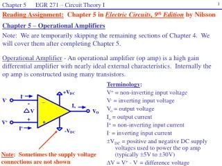
Chapter 5 :
Chapter 5 :. Processing . Or:. Detection of Signals in Noise and Clutters. Matched Filters. Output of a Matched Filter occurred in IF stage and : . Frequency response a Matched Filter: . S(f) is signal spectrum and t m is signal length . Example: A Rectangular Pulse.

Chapter 5 :
E N D
Presentation Transcript
Chapter 5 : Processing Or: Detection of Signals in Noise and Clutters
Matched Filters Output of a Matched Filter occurred in IF stage and : Frequency response a Matched Filter: S(f) is signal spectrum and tm is signal length Example: A Rectangular Pulse
Detection Criteria (Detection Decisions) 1.Neyman Pearson Observer: Based on a classical statistical theory for decision of detection • Have two types of errors : • 1. noise is detected as a target when noise is alone. False Alarm • 2. Signal is present, but it is erroneously considered to be noise. Missed Detection is probability function of signal plus noise 2.Likelihood Ratio Receiver: Based on statistical decision and define: 3. Inverse Probability Receiver: An analytical basis to model optimum receiver. This method is a academic interest and not practical for decisions. 4. Sequential Detection: • In Neyman Pearson Observer a number of pulses are considered for detection decision. • When S/N is large, no need to further pulses. A small number of pulse is sufficient to decision. This procedure is named as Sequential Detection.
Detectors 1. Optimum Envelope detector Law : Linear Detector IF Amp. Rectifier Video Amp. • Optimum detector is based on Likelihood Ratio Receiver : I0is model based Bessel function zero order and ais amplitude of the sin wave and vis amplitude of IF. • Suitable approximation is : • Linear Law Detector : • Have High dynamic range and preferred • For large of S/N we have a >>1 and then: • Square Law Detector : • Have distortion for signal • For small of S/N we have: • 2. Logarithmic Detectors : Logarithmic receivers • The output of the receiver is proportional to the logarithm of input envelope. • To prevent of saturation of receivers in non-MTI systems similar Log-FTC. • In MTI systems, nonlinearity is caused that the improvement factor is reduced. • The loss due to logarithmic detection is limited up to 1.1 dB with the increasing of number of pulses.
Detectors 3. I & Q Detector : In phase and quadrature phase channel Used in MTI for blind phase phenomena 3. Coherent Detector : Mixer • A single channel detector similar to in phase channel. • Reference single at the same exact frequency and same exact phase.
Automatic Detection Manual Detection (Operator Detection): PPI display or A-scope integrates pulses in operator’s eye memory. Automatic Detection and Tracking (ADT) act as following : • Quantization of the radar coverage into range (or angle) resolution cells. • Sampling at least one sample per cell or further. • Analog to digital conversion of input signal. • Signal processing in the receiver to remove noise, clutter and interference. • Integration of pulses in each resolution cell. • CFAR operation when the receiver don’t remove all clutter and interferences. • Clutter map generation to provide location of clutters. • Threshold detection to select of target echo. • Measurement of range and angle of the target. Automatic Detection (Machine Detection): By computer processing
Integration of Pulses In early radars : integration of pulses is performed by the operator’s eye memory in cathode ray tube (CRT) . In Modern radars : Several types of integrators are classified as following : • Moving window integrators. • Binary integration. • Batch integrators. • Feedback Integrators. • Mean Integrators. • Median integrators. • Censored (removed) mean detectors. • Adaptive detectors. • Non-parametric detectors. • Distribution detectors are usually considered as CFAR. • integration of pulses is performed by processing. • These integrators are called detectorsin technical literatures. Binary detector or Double detector or m-of-n detector • M pulse is sufficient from n pulse to detect Most of these detectors are academic interests and aren't applicable for operational radar systems
Integration of Pulses Optimum Number of Pulses in Binary integration: • Feedback Integrator:
Integration of Pulses Pulse Integration is categorized in two types • Coherent integration • Non-coherent integration
CFAR Receivers • A false alarm is an erroneous radar target detection decision caused by noise or other interfering signals exceeding the detection threshold. • The False Alarm Rate (FAR) is calculated using the following formula: • a threshold is set too high: Probability of Detection (P.d.) = 20% • bthreshold is set optimal: P.d. = 80% , but one false alarm arises!. False alarm rate = 1 / 666 = 1,5 x10⁻³ . • cthreshold is set too low: a large number of false alarms arises! • dthreshold is set variable, constant false-alarm rate is occurred . • If the threshold is set too low, the large number of false alarms will mask detection of valid targets. Different threshold levels
CFAR Receivers • Constant False Alarm Rate (CFAR) generate a adaptive threshold for detection decision. • Cell Averaging CFAR (CA-CFAR) : • Other form of CFAR : • Siebert CFAR: The old version of CFAR in 1960 for AN/FPS-23 ,US air force. • Hard limiter : It is a Dicke fix which hasa broad band IF amp. and a hard limiter and narrowband match filter. For anti jamming applications and impulse-like noise. • Log-FTC: It is a CFAR when the noise and clutter have a Rayleigh pdf.
CFAR Receivers • CFAR Loss is Defined as : Effect ofClutter’s Edges : • Clutter’s Edges are change threshold level. • GO-CFAR reduces this effect by using the greater of the two sets of reference cells. • GO-CFAR introduces an additional loss of 0.1-0.3 dB. Effect ofMultiple Targets: • Multiple targets in res. cells increase threshold level. • In this case a number of res.cells is removed (censored). • This procedure is called ‘’Censored Mean Level Detector’’ (CMLD). • Other method for canceling multiple targets is ‘’ordered statistic’’ (OS-CFAR)
Signal Management • Signal Processing: Signal processing is detection targets in noise, clutter and interference such as: • Matched filter to maximize S/N. • Detector/ Integrator. • Clutter reduction. • CFAR. • Electromagnetic compatibility (EMC). • Electromagnetic Counter Countermeasures (ECCM). • Threshold detection. • Data Processing: Data processing is actions after detection of target such as: • Target location: in range angle velocity and ... • Target trajectory: target track that is the time history target location. • Target recognition: type of target e.g. recognition of aircraft from birds and ... • Weapon control : in fire control systems (FCS).