Download
1 / 30
320 likes | 779 Views
Understand the principles, operation, efficiency, and applications of transformers in electrical power systems. Learn about basic transformer construction, losses, efficiency calculations, and practical considerations.

E N D
Electromechanical Systems Unit 5 Transformers
This unit explains Conversion of electrical power at one alternating voltage and current level to another, with little power loss Conversion does not involve any moving parts After completing this unit you should be able to Describe the principles of an ideal transformer. Analyse the operation of such a transformer. Calculate the efficiency of a transformer with I2R and core losses Summary and Learning Outcomes
Basic Transformers Transformer Losses Transformer Efficiency Content
AC Power Distribution Network Some other common Applications • Isolation (two grounds) • Voltage and Current sensing
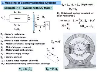
Basic Transformers Primary steel core • A simple single phase transformer comprises a steel core onto which two separate coils are wound. • The core is laminated to minimise eddy current losses. • The coil connected to an alternating current (ac) the supply, is called the “primary winding”. • The coil connected to the load, is termed the “secondary winding”. • Transformers can be used as Step up or Step down transformers
Basic Transformers • Time-varying flux will induce a voltage, and hence a current. • Time-varying flux also affects the magnetic core, and the induced voltage will cause “eddy” currents in the core, which depend on the resistivity of the core. • These currents dissipate energy in the form of heat. • Eddy currents are reduced by selecting: • High-resistivity core materials, or by • Laminating the core, introducing tiny, discontinuous air gaps between core layers. • Therefore, lamination of the core reduces eddy currents greatly withoutaffecting the magnetic properties of the core.
Basic Transformers, Open Circuit E1 E1 • Open circuit means that there is no load connected to the secondary winding • A sinusoidal voltage V1|across the primary winding|, which has N1 turns. • A small magnetising current I1 will flow in that winding and establish a flux in the core - (just like the toroid coil). • The flux induces an emf E1 in the primary coil in accordance with Faraday’s Law.
The flux (1) is common to both coils it will also induce an emf E2in the secondary winding, which has N2turns • From E1we had From E1 and E2 • “turns ratio” or “transformation ratio =
& We had “turns ratio” = • If the primary & secondary impedances are negligible, then: • E1=V1, applied voltage • E2=V2, secondary terminal voltage
In practice: • The windings will have a small finite resistance, and • A very small fraction of the flux will fail to link both coils.This we refer to as Flux Leakage • Fortunately, the effects of these are generally small and may be ignored allowing the above equations to be used with reasonable accuracy.
Load Connected to The Secondary Since • A current I2 will start to flow when a load is connected to the secondary circuit. • I2 will set up its own flux 2, in a direction which will opposethe main flux , tending to reduce it and eventually reducing E1
The potential difference (V1 - E1)in the primary circuit increases • Raises both the primary current I1 and the main flux. i.e. I1 &1 • Equilibrium is achieved when the flux (hence E1) has been restored to its original value • The extra flux produced by the increase in the primary current cancels out the flux 2 created by I2. • In the steady state the mmfs (ampere turns) in the primary and secondary windings balance i.e. I1N1 = I2N2 or
I2 2opposing 1 1 E1 (V1 - E1) I1 1counteract 2 2 E2 (V2 – E2) I2 and so on a balance is reached • In the steady state the mmfs (ampere turns) in the primary and secondary windings i.e. I1N1 = I2N2 or
I2R Losses These are losses in both, the primary and the secondary Losses are due to the resistance of the coils, hence losses in each of the windings is equal to I2R These losses translate as heat and are often referred “copper losses”. Transformer Losses There are two types of losses in a transformer, namely: • Core Losses • Two types of losses caused by: • Magnetic hysteresis effects, and • Eddy current losses in the steel core. • constant and independent of load.
Transformer Efficiency • Efficiency, Input power = Output power + (I2Rlosses) + (core losses) Output power = P2 = V2 I2 cos2where (cos2) = power factor of the load Primary (I2 R) Losses, P11 = I12 R1 & Secondary (I2 R) Losses, P12 = I2 2R2 Total Core loss, Pc = hysteresis loss + eddy current loss (= constant) Input power = P1 = P2 + (P11 + P12) + Pc
I1 I2 = aI1 E2 = V2 V1 = E1 E2 =E 1 / a Transformer Equivalent Circuit • Ideal Transformer • The losses are zero in an ideal transformer. Therefore the input power (VA) is equal to the output power (VA). • I1 V1 = I2 V2 • The voltage and current relations are: • a = V1/V2 = I2/I1 or V2 =V1/a & I2= I1 a • If a transformer increases the voltage, the current decreases and vice versa.
Exercise A 200V:50V 60Hz transformer supplies a load comprising a 10 resistor in series with a 100mH inductor. Calculate the primary current.
Exercise, Impedance Transformer Find the equivalent load impedance seen by the voltage source (i.e., reflected from secondary to primary) for the transformer in the Figure By definition, the load impedance is equal to the ratio of secondary phasor voltage and current: Z2 = V2/I2 To find the reflected impedance we can express the above ratio in terms of primary voltage and current: where the ratio V1/I1 is the impedance seen by the source at the primary coil, that is, the reflected load impedance seen by the primary (source) side of the circuit. Thus, we can write the load impedance, Z2, in terms of the primary circuit voltage and current; we call this the reflected impedance, Z’2:
By definition, the load impedance is equal to the ratio of secondary phasor voltage and current: Z2 = V2/I2 To find the reflected impedance we can express the above ratio in terms of primary voltage and current: where the ratio V1/I1 is the impedance seen by the source at the primary coil, that is, the reflected load impedance seen by the primary (source) side of the circuit. Thus, we can write the load impedance, Z2, in terms of the primary circuit voltage and current; we call this the reflected impedance, Z’2: Thus, Z’2= α2Z2, as shown in the bottom figure, which depicts the equivalent circuit with the load impedance reflected back to the primary.
Exercise A 60kVA 1200V:240V single phase transformer dissipates 2kW when its secondary is open-circuited. The resistance of the primary (high voltage) winding is 0.8 and the resistance of secondary is 0.04. Calculate the efficiency of the transformer when it supplies full load at 0.8 power factor lagging. [88.1%]
Smoothing Capacitor • To calculate the precise value of smoothing capacitance required for a particular application can be difficult as • The rise in capacitor voltage is sinusoidal, and • The fall is exponential. • However, a reasonably accurate approximation may be found by assuming that both the rise and fall are linear.
Smoothing Capacitor VR • If maximum peak to peak ripple voltage = Vr • Average DC output voltage • During the discharge time from , the only current that flows • is that through the capacitor and load resistor.
Smoothing Capacitor 1 • We know that , • however, by assuming that the drop in voltage is linear, • and the current I is constant, this simplifies to where v = total change (fall) in voltage t = discharge time. In this case: Fall in voltage = ripple voltage, Vr Capacitor current, IC = load resistor current =
Substituting in Large Capacitor If the ratio Ripple-less output voltage 1 The discharge time stretches from to Substituting this back in gives: discharge time, IC =
In full wave bridge rectifier there are twice as many pulses, therefore, • Halving the capacitor discharge time. • As a result the required smoothing capacitance Smaller Capacitor Farads
Conclusion Today we studied: • Transformers: • Conversion of ac|voltage -current from one level to another, with little power loss • Conversion does not involve any moving parts • Described the principles of an ideal transformer: • Analysed its operation. • Looked at I2R and core losses • We will look at Core losses in more details in the future • Calculated the efficiency • Revised RC Smoothing from Last week
A 240V:12V 50Hz transformer supplies a secondary (low voltage) load comprising 3 resistor and 12.7mH inductor. Calculate the primary current. [0.12 –53.1 A] • A 240V:120V 60Hz transformer has its low voltage winding connected to 120V supply. Across the high voltage winding is a resistor in series with a capacitor. The supply current is (0.8 + j0.6)A. Calculate the resistance and capacitance. [384, 9.2F] • When a 100kVA 3.3kV : 240V 50Hz single phase transformer is operated at full load, 0.8 power factor, the total (I2R) loss and core loss are both 1kW. Calculate the efficiency when the transformer operates at half load 0.8 power factor. [97.0%] • When a 15kVA 1500V : 150V 50Hz single phase transformer is operating at full load unity power factor the total (I2R) loss and core loss are equal and the efficiency is 98%. • Calculate the core loss: [153W] • During one day the transformer loading cycle is • 12 hours at 4kW output, 0.5 power factor • 8 hours at 12kW output, 0.98 power factor • 4 hours at 9kW output, 0.9 power factor. • Calculate • total output energy in the day [180kWh (=648MJ)] • input energy during each of the three periods and total input energy in the day.[50.33kWh (181MJ), 98.04kWh (353MJ), 36.88kWh (132.7MJ), 185.27kWh (666.9MJ)] • Given that all day efficiency = , find the all day efficiency. [97%] Problems