Download
1 / 51
530 likes | 693 Views
Learn to calculate flux, flux density, MMF, and magnetic field strength. Delve into Faraday’s law, Lenz’s law, and Ampere’s law, understanding the relationship between electricity and magnetism in different materials and structures. Explore MMF sources, magnetic field intensity, and flux density variations. Master concepts with practical examples.

E N D
Electromechanical Systems Unit 6 Electromagnetism 1
Summary and Learning Outcomes After completing this unit you should be able to calculate • Flux • Flux density • Magneto motive force • Magnetic field strength Content • Magnetic Fields • Toroidal Coil • Energy Losses 2
Faraday’s law • If the imaginary surface A were bounded by a conductor (for example, the thin wire in figure) then a changing magnetic field would induce a voltage, and therefore a current, in the conductor. Faraday’s law states that • If the imaginary surface A were bounded by a conductor (for example, the thin wire in figure) then a changing magnetic field would induce a voltage, and therefore a current, in the conductor. • More precisely, Faraday’s law states that: A time-varying flux causes an induced electromotive force, or emf, e: • More precisely: A time-varying flux causes an induced electromotive force, or emf, e: x • If the magnetic field (the flux) within the coil, is constant, then no voltage will exist across terminals a and b • if, however, the flux were increasing and terminals a and b were connected (by a resistor), then current would flow in the coil in such a way that the magnetic flux generated by the current would oppose the increasing flux y x y 3
Lenz’s law • The flux induced by a current would be in the direction opposite to that of the original flux density vector, B. • Hence, The reaction flux would then point downward in the upper figure or into the page in lower figure. B • Flux Increasing: The increasing flux would induce a current flowing clockwise in the figure • Current flows out of terminal b and into terminal a. • The resulting voltage across R would then be negative. • Flux decreasing: The decreasing flux would induce a current in the coil so as to reestablish the initial flux • This would mean that the current would have to generate a flux in the upward direction. • Thus, the resulting voltage would change sign. x y x y 4
Ampere’s Law • Faraday’s law is one of two fundamental laws relating electricity to magnetism. • Ampere’s law is the second fundamental relationship that relates electricity to magnetism. It states that the magnetic field intensity, H, in the vicinity of a conductor is related to the current carried by the conductor; thus Ampere’s law establishes a dual relationship with Faraday’s law. • Faraday’s law is one of two fundamental laws relating electricity to magnetism. • The second fundamental relationship that relates electricity to magnetism states that the magnetic field intensity, H, in the vicinity of a conductor is related to the current carried by the conductor; thus this relationship establishes a dual relationship with Faraday’s law. 5
Ampere’s Law Relative permeabilities for common materials 6
Ampere’s Law Permeability Flux density magnetic field intensity It follows that a given magnetic field intensity, H, will give rise to different flux densities in different materials. 7
MMF and Ampere’s Law Let us define sources of magnetic energy, in terms of the magnetic field intensity, so that different magnetic structures and materials can then be evaluated or compared for a given source. • Lets name this “source” as magnetomotive force (mmf). • Remember, both the magnetic flux density (B) and field intensity (H) are vector quantities • However, for ease of analysis, scalar fields will be chosen by appropriately selecting the orientation of the fields. • Ampere’s lawstates that the integral of the vector magnetic field intensity, H, around a closed path is equal to the total current linked by the closed path, i: • where dl is an increment in the direction of the closed path. • If the path is in the same direction as the direction of the magnetic field, we can use scalar quantities to state that 8
|from previous page Now, lets consider the simple case of a current “i” carrying wire and a circular path|radius r surrounding the wire: • The magnetic field intensity, H, is determined by the familiar right-hand rule. • If the direction of the current ipoints in the direction of the (right-hand) Thumb, the resulting magnetic field encircles the conductor in the direction in which the other four fingers would encircle it. • Thus, the closed-path integral becomes equal to H.(2r), since the path and the magnetic field are in the same direction • Therefore the magnitude of the magnetic field intensity is given by 9
The magnetic field intensityis unaffected by the material surrounding the conductor, • But the flux density depends on the material properties [as B =μH] • Thus, the density of flux lines around the conductor would be far greater in the presence of a magnetic material than if the conductor were surrounded by air. Flux density lines around the conductor|in the presence of a magnetic material >> Conductor|surrounded by air • The field generated by a single conducting wire is not very strong; • however, if we arrange the wire into a tightly wound coil with many turns, we can greatly increase the strength of the magnetic field. The product N.i is a useful quantity in electromagnetic circuits, and is called F F=N . i Ampere-Turns (A.t) The magnetomotive force mmf 10
Materials • When a material is placed within a magnetic field, the magnetic forces of the material's electrons will be affected. • This effect is known as Faraday's Law of Magnetic Induction. However, materials can react quite differently to the presence of an external magnetic field, depending on a number of factors, such as: • The atomic and molecular structure of the material, and • The net magnetic field associated with the atoms. • The magnetic moments associated with atoms have three origins: • The electron orbital motion, • The change in orbital motion caused by an external magnetic field, • The spin of the electrons. 11
In most atoms, electrons occur in pairs. • Electrons in a pair spin in opposite directions and their opposite spins cause their magnetic fields to cancel each other. Therefore, no net magnetic field exists. • Alternately, materials with some unpaired electrons will have a net magnetic field and will react more to an external field. • Most materials can be classified as • diamagnetic, • paramagnetic or • ferromagnetic. 12
Diamagnetic • These metals have a very weak and negative susceptibility to magnetic fields. • Diamagnetic materials are slightly repelled by a magnetic field and the material does not retain the magnetic properties when the external field is removed. • They are solids with all paired electron resulting in no permanent net magnetic moment per atom. Diamagnetic properties arise from the realignment of the electron orbits under the influence of an external magnetic field. • Most elements in the periodic table, including copper, silver, and gold, are diamagnetic. Paramagnetic • Have a small and positive susceptibility to magnetic fields. • They are slightly attracted by a magnetic field and the material does not retain the magnetic properties when the external field is removed. • Paramagnetic properties are due to the presence of some unpaired electrons, and from the realignment of the electron orbits caused by the external magnetic field. • Paramagnetic materials include magnesium, molybdenum, lithium, and tantalum. 13
Ferromagnetic • Have a large and positive susceptibility to an external magnetic field. • They exhibit a strong attraction to magnetic fields and are able to retain their magnetic properties after the external field has been removed. • Ferromagnetic materials have some unpaired electrons so their atoms have a net magnetic moment. • They get their strong magnetic properties due to the presence of magnetic domains. • In these domains, large numbers of atom's moments (1012 to 1015) are aligned parallel so that the magnetic force within the domain is strong. • When a ferromagnetic material is in the unmagnitized state, the domains are nearly randomly organized and the net magnetic field for the part as a whole is zero. • When a magnetizing force is applied, the domains become aligned to produce a strong magnetic field within the part. • Iron, nickel, and cobalt are examples of ferromagnetic materials. • Components with these materials are commonly inspected using the magnetic particle method. 14
Magnetic Flux density and Ferromagnetic Materials • The magnetic field generated by the coil can be made to generate a much greater flux density if the coil encloses a magnetic material. • The most common ferromagnetic materials are steel and iron; in addition to these, many alloys and oxides of iron as well as nickel—and some artificial ceramic materials called ferrites also exhibit magnetic properties. • Winding a coil around a ferromagnetic material accomplishes two tasks at once: • It forces the magnetic flux to be concentrated near the coil, and • If the shape of the magnetic material is appropriate, completely confines the flux within the magnetic material, thus forcing the closed path for the flux lines to be almost entirely enclosed within the ferromagnetic material. 15
Typical arrangements are: • Iron-core inductor and • the toroid • The flux densities for these inductors are given by the expressions: • Tightly wound circular coil • Toroidal coil Iron-core inductor 16 Toroid
Simple Magnetic Core • N turns of wire wrapped about one leg of the core • The core is composed of iron or certain other similar metals (collectively called ferromagnetic materials) • The current passing within the path of integration, Ampere’s law thus becomes • Hlc = Ni • where, H is the magnitude of the magnetic field intensity vector H 17
Units • ‘H’ are Ampere-Turn per meter (AT/m) • ‘’ are Henry per meter (H/m) • ‘B’ are Weber per meter (Wb/m2) or Tesla (T) Permeability of: • free space, 0 = 4 x 10⁻⁷ H/m • r = /0(Steel has rof 2000 to 6000) 18
Magnetic Field • Because the permeability of iron is much higher than that of air, the great majority of the flux in an iron core remains inside the core instead of traveling through the surrounding air, • Hence in a core, the flux density B = H = [Ni]/lc • The total flux in a given area is given by = BA = Where A is the cross-sectional area of the core dA is the differential unit of area = BA = [NiA]/lc • In the last equation of total flux, the current in a coil of wire wrapped around a core produces a magnetic flux in the core. This analogous to a voltage in an electric circuit producing a current flow. • It is possible to define a “magnetic circuit” whose behavior is governed by equations analogous to those for an electric circuit. 19
Simple Electric/Magnetic Circuit • It is possible to analyze the operation of electromagnetic devices by means of magnetic equivalent circuits. • Before we can present this technique, we need to make a few simplifying approximations: • The first of these approximations assumes that there exists a mean path for the magnetic flux, and • The corresponding mean flux density is approximately constant over the cross-sectional area of the magnetic structure. 20
Thus, a coil: • wound around a core with cross-sectional area A • will have flux density • By knowing the flux density, we obtain the field intensity: • knowing the field intensity, we can relate the mmf of the coil, F, to the product of the magnetic field intensity, H, and the length of the magnetic (mean) path, l, for one leg of the structure: “A”is assumed to be perpendicular to the direction of the flux lines 21 F = N .i = H .l F= S =Ni WhereF = magnetomotive force of the circuit = flux of the circuit S= reluctance of the circuit
We had: F = N .i = H .l Therefore, the mmf is equal to the magnetic flux times the length of the magnetic path, divided by the permeability of the material times the cross-sectional area. 22 F= S =Ni WhereF = magnetomotive force of the circuit = flux of the circuit S= reluctance of the circuit
A review of this formula reveals that: • The magnetomotive force,F The voltage source in electrical circuit • The flux, φ The electrical current in a circuit, and • The term l/μA The magnetic resistance of one leg of the magnetic circuit. • The resistance of a cylindrical conductor of length “l” and cross-sectional area “A”, • Permeability, μ, The conductivity, σ. • l/μA is assigned the name of Reluctance, and is given the symbol R. • Just as the • “Conductanceis the reciprocal of its Resistance|electric circuit ”, • “Permeance is the reciprocal of its Reluctance”| magnetic circuit 23
The relationship between the reluctance of a magnetic structure and its inductance. 25
Magnetic Circuit The relationship between magnetomotive and flux can thus be expressed as F = R By comparing this equation and (F= R), we see that the reluctance of the core is 26
Reluctance • Reluctance's|magnetic circuit obey the same rules as resistances|electric circuit. • The equivalent reluctance of number of reluctance's • in series • in parallel 27
Example 1 • The magnetic structure and its equivalent circuit analogy is shown in the above figure. We see that • The mmf, F = Ni, excites the magnetic circuit, • The circuit is composed of four legs: • two legs of mean path length l1 and cross-sectional area A1 = d1w, • two others of mean length l2 and cross section A2 = d2w. • Thus, the reluctance encountered by the flux in its path around the magnetic core is given by series=21 + 22 (where 1=l1 / μA1 & 2 = l2 / μA2) 28
Remember! • In the result we obtained • series=21 + 22 , with 1=l1 / μA1& 2 = l2 / μA2 • we assumed that: All of the magnetic flux is linked by all of the turns of the coil. The flux is confined exclusively within the magnetic core. The density of the flux is uniform across the cross-sectional core’s area. 29
Example 2 Calculate the flux, flux density, and field intensity on the magnetic structure of Figure. Known Quantities: μr=1,000; N=500 turns; i=0.1A. Find: φ; B; H. Assumptions: All magnetic flux is linked by the coil; The flux is confined to the magnetic core; The flux density is uniform. Method of handling such Questions Calculate the magnetomotive force: F = mmf = Ni [50 A.t] Calculate a mean path that runs through the geometric center of the magnetic structure. [0.36 m] The cross sectional area is A = w2 [0.0001 m2]. Calculation of reluctance [2.865×10⁶ A.t/Wb] Draw Equivalent Circuit Calculation of magnetic flux, φ; flux density ,B; and field intensity, H . 30
Calculate the flux, flux density, and field intensity on the magnetic structure of Figure. Known Quantities: μr=1,000; N=500 turns; i=0.1A. Find: φ; B; H. Method of handling such Questions Calculate the magnetomotive force: F = mmf = Ni Estimate the mean path of the magnetic flux. Calculate a mean path that runs through the geometric center of the magnetic structure. The cross sectional area is A = w2 Calculation of reluctance Draw Equivalent Circuit Calculation of magnetic flux, φ; flux density ,B; and field intensity, H . 31
Calculate the flux, flux density, and field intensity on the magnetic structure of Figure. Known Quantities: μr=1,000; N=500 turns; i=0.1A. Find: φ; B; H. 32
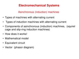
Magnetic Fields • The magnetic fields associated with a bar magnet and a straight coil are very similar • Because of the fringing of the fields both are difficult to analyse. • It is far easier to study fields which are contained within defined boundaries. • We will start with the toroidal coil 33
Toroidal Coil B = H where = permeability in Hm-1 For non-magnetic materials: permeability = constant, o, which is called the permeability of free space Where: o= 4 10-7 Hm-1 And B = oH For magnetic materials: = or where r = relative permeability. mmf = flux reluctance iN = S • mmf is measured in A (amperes), • flux is in Wb (webers) • reluctance is in H-1 (henries-1) Magnetic field strength, Am-1 where l = length of magnetic path in metres. Flux density, B is defined as T (tesla) where A = cross sectional area of magnetic path in m2 34
36 Flux density B, varies with magnetic field strength, H
A cylindrical toroid manufactured of silicon steel with a mean diameter 10cm, radial x-sectional area of 6x10⁻⁴m2is wrapped with a coil of 1178 turns, carrying a current of 1.6A. Calculate the magnetic flux, in the core. l= D = 10 10-2 = 0.1 metres A = 6 10-4 m2 N = 1178 H = = = 1.6 = 6000 Am-1 from B Vs H graph, B = 2.0T = BA = 2.0 6 10-4 = 1.2 10-3 Wb = 1.2 mWb 37
A 1mm wide radial cut is made in toroid core steel with a x-sectional area of 6x10⁻⁴m2. Calculate the current required to maintain the flux at 1.2mWb • Modified forms of Kirchoff’s laws are used to analyse magnetic systems: • The algebraic sum of fluxes entering and leaving a junction is zero. • = 0 • The algebraic sum of “mmf drops” (Hl) around a closed loop is zero. • (Hl) = 0 • Utilising these “laws”. Driving mmf, iN = Hsteel lsteel + Hairlair Considering the air gap: lair = 1 10-3 metres We know , hence we can calculate B Assuming that the flux crosses the air gap without fringing, (i.e. the flux density in the air gap will be the same as that in the steel) Bair=Bsteel We know B, then we can calculate H B = 0Hair Calculate Hsteel /A Calculate i iN = Hsteel lsteel + Hairlair 38
Hairlair = 1.592 106 1 10-3 = 1592 A considering the steel: lsteel = D - lair = 0.1 - (1 10-3) = 0.3132 m with the flux density unchanged Hsteel remains unchanged. Note that Hsteel may be found from the graph as 6000 Am-1 Hsteellsteel = 6000 x 0.3132 = 1879 A iN = 1879 + 1592 = 3471 “driving” mmf, iN = Hsteel lsteel + Hairlair considering the air gap: lair = 1 10-3 metres assuming that the flux crosses the air gap without fringing the flux density in the air gap will be the same as that in the steel i.e. for air, B = 0Hair 39
A steel ring with a mean circumference 0.75m and cross sectional area 5cm2 is wound with a coil of 120 turns. Given the following B/H characteristic for the steel draw a graph of flux vs. current for the toroid. = BA 40
Iron Losses • When an alternating current flows in a coil wound around an iron or steel core: • Hysteresis and • Eddy current • losses will be produced in the core. • These losses will be manifested as heat. 42
Energy Losses in Ferromagnetic Cores b Applying an alternating current instead of direct current with the assumption that the flux in the core is initially zero c a e Residual Flux Coercive MMf Fc d 43
As the current increases for the first time, the flux in the core traces out path ab • However, when the current falls again, the flux traces out a different path from the one it followed when the current increased b c a e Residual Flux • As the current decreases, the flux in the core traces out pathbcd, and later when the current increases again, the flux traces out path deb. Coercive MMf Fc d • Notice that the amount of flux present in the core depends not only on the amount of current applied to the windings of the core, but also on the previous history of the flux in the core, failing to retrace flux path is called hysteresis • Path bcdeb is called a hysteresis loop. 44
Magnetic Hysteresis b c a e d 45
Energy Losses in Ferromagnetic Cores • The hysteresis loss in an iron core is the energy required to accomplish the reorientation of domains during each cycle is the energy required to accomplish the orientation of domains during each cycle of the alternating current applied to the core. • Another type of loss is eddy current loss Both hysteresis and eddy current losses cause heating in the core material Hence must be considered in the design of any machine or transformer. Since the losses occur within the metal of the core, they are lumped together and called as core losses 46
Eddy Current Losses • The ac flux induces emfs in the core, which in turn produced eddy currents that circulate in the iron. • The iron in the magnetic circuits is laminated to prevent excessive eddy currents. • Molded Ferrites are used in solid form for some high-frequency applications. • The plane of the laminations is parallel to the flux, thus confining the eddy current to paths of small cross section and correspondingly high resistance. 47
Both hysteresis and eddy current losses cause heating in the core material Hence must be considered in the design of any machine or transformer. Since the losses occur within the metal of the core, they are lumped together and called as core losses 48
Applications in Electromagnetics • A current-carrying wire produces a magnetic field in the area around it. • Ampere’s Law • A time-changing magnetic field induces a voltage in a coil of a wire if it passes through that coil. • Transformer Principle • A current carrying wire in the presence of a magnetic field experiences a force induced on it. • Motor Principle • A moving wire in the presence of a magnetic field has a voltage induced in it. • Generator Principle 49
Conclusions In this unit, we mainly examined • Analysis of Electromagnetic systems such as Toroidal Coil • The Analysis considered • Flux • Flux density • Magneto motive force • Magnetic field strength • Energy Losses 50