DC Circuits: Principles and Analysis
Gain a deep understanding of DC circuits, resistive circuits, Kirchhoff's Laws, and circuit analysis. Learn about power and energy dissipation, bridge measurements, inductance, and capacitance. Explore Ohm's Law, Wheatstone Bridge, and more.

DC Circuits: Principles and Analysis
E N D
Presentation Transcript
Electromechanical Systems Unit 1 DC Circuits 1
Aims • To improve your knowledge of the basic principles of electrical and electronic engineering. • To evaluate basic circuits, to compute fundamental parameters, and to analyse the operation of electronic equipment and electrical power apparatus. • To enable you to select the most appropriate equipment for a particular application later in your career.
Learning Outcomes • To remind you of some of the basic principles of electricity and electronics that you have met in your pre-university education. • After completing this unit you should be able to:- • Calculate the equivalent resistance of a DC circuit and determine the power and energy dissipation. • Compute changes in strain and temperature from measurements taken with a Wheatstone Bridge. • Calculate the energy stored in inductors and capacitors.
Contents 1.1 Resistive Circuits 1.2 Kirchoff’s Laws 1.3 Circuit Analysis 1.4 Power and Energy Dissipation 1.5 Bridge Measurements 1.6 Inductance 1.7 Capacitance
1.1.1 Ohm’s Law Fig 1.1.1
1.1.1 Ohm’s Law ….(1.1.1a) ….(1.1.1b) Fig 1.1.1
1.1.2 Series Circuits ….. (1.1.2) Fig 1.1.2
1.1.3 Parallel Circuits …….. (1.1.3) Fig 1.1.3
1.1.4 Series / Parallel Circuits The resistance may be calculated by systematic reduction of the network 1.Replace parallel section of R3andR4byequivalent resistance R6 where Fig 1.1.4a
2. Replace resistors in series R5and R6 with equivalent resistance Try to complete the process and prove that Total Resistance Fig 1.1.4a
1.2 Kirchoff’s Laws German-Berlin 12 March 1824 – 17 October 1887 • In 1845 Kirchhoff developed the laws governing current & resistance in electrical networks. • He is also famous for inventing (with Robert Bunsen) the spectroscope, in 1859.
1.2.1 Kirchhoff’s Current Law The algebraic sum of currents entering and leaving a node (junction) is zero I2 “The algebraic sum of the currents at a node must be equal to zero” I1 I3 I1 + I2 – I3 + I4 – I5 =0 I5 I4
The algebraic sum of potential differences (voltages) around a closed loop is zero V V1 V2 V3 “The net voltage in a closed circuit is zero”
The current flow and voltage distribution in any electrical or electronic circuit can be determined. • It is not essential for you to know these methods for this module • But you might find them useful if you take optional modules in electricity and electronics.
In a D.C. resistive circuit Power = Voltage Current P = V I watts Energy = Power time W = P.t Joules Power dissipated in a resistor = I2R Watts
1.5 Wheatstone Bridge British scientist: 6 February 1802 - 19 October 1875 Best known for his contributions in the development of the Wheatstone bridge, 1843. The Bridge was originally invented by Samuel Hunter Christie in 1933. Used to measure an unknown electrical resistance, and as a major figure in the development of telegraphy.
1.5.1 Wheatstone Bridge When the bridge is balanced no current flows through the galvanometer The voltages at nodes 2 and 3 are equal, therefore,
Steps to measure strain of a strain gauge • Replace the resistor RB by a strain gauge. • Adjust RD to balance the bridge • As the test starts, the resistance of the strain gauge changes depending on the strain • This creates unbalance of resistance in the bridge, creating a voltage difference between the nodes 2 and 3 • Let RB be the change in resistance • Voltmeter reading ……… (1.5.2a) strain, strain gauge factor, G
Steps to measure strain of a strain gauge (cont…) …….. (1.5.2b) Substitute equation 1.5.2b in equation 1.5.2a Strain,
Steps to measure temperature of a thermistor • To monitor temperature replace the resistor RB by a thermistor. • Repeat the steps as that of the strain measurement …… (1.5.2c) Substitute equation 1.5.2c in equation 1.5.2a
It is used to minimize the errors due to change in surrounding conditions • Changes in resistance might be very small (e.g. for a bonded foil strain gauge 0.25m per microstrain). • a strain gauge which is sensitive to thermal changes would be compensated by incorporating in the bridge circuit an unstrained “dummy” gauge • which is subjected to the same temperature variations as the measuring device.
Sensitivity can be increased by using two active gauges as in the example of strain measurements on a cantilever
A coil of N turns is wrapped around a toroid. • When a current i flows in the coil • a magnetomotive force (mmf) equal to iN ampere-turns* is produced • a magnetic flux is established. • *Strictly magnetomotive force has the units of amperes (as turns have no units), however, as the magnitude of the flux is dependent on the (current number of turns) it is often easier to consider the units of mmf to be ampere-turns. mmf = flux reluctance
It is one of the most fundamental laws of electromagnetic systems. • states that the “voltage induced in a circuit = rate of change of magnetic flux linkage” • mathematically, Where equals the inductance, L, of the coil in henries
When the switch is closed current starts to flow in the inductor establishing a voltage, e, across the coil which opposes the current Instantaneous power = instantaneous voltage instantaneous current
1.6 Inductance (Cont…) Energy supplied in dt = = Total energy supplied = joules = Note: We will examine inductive circuits more comprehensively in Unit 6 - Electromagnetism
1.7.1 The Capacitor When a voltage, V is applied to the plates they will eventually became charged at equal magnitude |Q|, but with opposite sign. Total charge where C = capacitance in farads = electrostatic field characteristic known as the permittivity
For free space (or vacuum): = 8.85 x 10⁻¹² Fm-1 For other dielectric materials (like mica, paper, air, porcelain): where r = relative permittivity
1.7.2 Energy stored in a Capacitor Assuming that the capacitor is initially uncharged. When the switch is closed a current will flow until the voltage across the capacitor is equal to the voltage source. Instantaneous current, where v = instantaneous voltage
instantaneous power = instantaneous voltage instantaneous current Energy supplied in dt Total energy supplied joules =
Further Readings • “Electrical and Electronic Technology,” • by Edward Huges • “Engineering Circuits Analysis,” • by Durbin • “fundamental of Electrical Engineering,” • by Bobrow
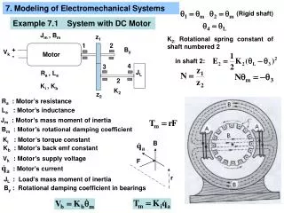
Problem 1 Calculate the equivalent resistance of the circuit shown in Fig Q1.1 and hence find the current and power supplied by the battery. Fig. Q1.1
Problem 2 A strain bridge comprises two 150 resistors, one active gauge and one unstrained gauge for temperature compensation. The two gauges have unstrained resistances of 150 and a strain gauge factor of 2.5. The bridge supply voltage is 5V. Calculate the strain when the voltmeter reading is 2mV.
Problem 3 A toroid wound with a coil of 400 turns has a reluctance of 500 000 H-1. Calculate its inductance. A steady current of 2A flows through the coil. Find the flux and stored energy.
Problem 4 A capacitor comprises two strips of aluminium 30cm x 15cm separated by a strip of mica 2mm thick. The relative permittivity of mica is 6.0. Calculate the capacitance. A voltage of 250V is applied across the capacitor. Calculate the stored energy.