ELECTROMECHANICAL ENERGY CONVERSION
CHAPTER 3. ELECTROMECHANICAL ENERGY CONVERSION . Electrical energy is the most popular form of energy, because:. 1. it can be transmitted easily for long distance, at high efficiency and reasonable cost. 2. It can be converted easily to other forms of energy such as

ELECTROMECHANICAL ENERGY CONVERSION
E N D
Presentation Transcript
CHAPTER 3 ELECTROMECHANICAL ENERGY CONVERSION
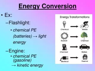
Electrical energy is the most popular form of energy, because: 1. it can be transmitted easily for long distance, at high efficiency and reasonable cost. 2. It can be converted easily to other forms of energy such as sound, light, heat or mechanical energy.
Hidro power station, Kenyir Terengganu Power consumers, JB Johor
Electrical energy Sound energy Loud speaker Electrical energy Light energy Lamp Heat energy Electrical energy Kettle
Electromechanical energy conversion device: converts electrical energy into mechanical energy or converts mechanical energy into electrical energy.
There are various electromechanical conversion devices may categorized as under: a. Small motion - telephone receivers, loud speakers, microphones b. Limited mechanical motion - electromagnets, relays, moving-iron instruments, moving-coil instruments, actuators c. Continuous energy conversion - motors, generators
Principle of Energy Conversion According to the principle of conservation of energy, energy can neither be created nor destroyed, it can merely be converted from one form into another. The total energy in a system is therefore constant.
Energy conversion in electromechanical system In an energy conversion device, out of the total input energy, some energy is converted into the required form, some energy is stored and the rest is dissipated. It is possible to write an equation describing energy conversion in electromechanical system: Electrical energy from source Mechanical energy to load Increase of field energy Energy converted to heat (losses) + + = 3.1
Electrical energy from source Energy converted to heat (losses) Mechanical energy to load Increase of field energy + + = 3.1 The last term on the right-hand side of Eq. 3.1 (the losses) may be divided into three parts: Energy converted to heat (losses) Friction and windage losses Resistance losses Field losses + + = 3.2 Then substitution from Eq. 3.2 in Eq. 3.1 yields
Mechanical energy to load plus friction and windage losses Electrical energy from source minus resistance losses Increase of magnetic coupling field energy plus core losses 3.3 = + Now consider an electromechanical system (actuator) illustrated in Fig. 3.1.
Fixed steel core g Moveable steel armature SW Figure 3.1
At any instant, the emf e induced in the coil by the change in the flux linkage is volt 3.4 Consider now a differential time interval dt, during which the current in the coil is changing and the armature is moving.
Therefore, the differential energy transferred in time dt from the electric source to the coupling field is given by the energy output of the source minus the resistance loss: Joule 3.5
The coupling field forms an energy storage to which energy supplied by the electric system. At the same time, energy is released from the coupling field to the mechanical system. The rate of release energy is not necessarily equal at any instant to the rate of supply of energy to the field, so that the amount of energy stored in the coupling field may vary.
It’s like a pipe system in our house. Water tank The water out from the tap will make water flow into the storage tank from the supply.
It’s like a pipe system in our house. Water tank The water out from the tap will make water flow into the storage tank from the supply.
In time dt, let dWf be the energy supplied to the field and either stored or dissipated. Let dWm be the energy converted to mechanical form, useful or as loss, in the same time, dt. Then, by the principle of conservation of energy, the following equation may be written for the field: 3.6
Field Energy To obtain an expression for for dWf of Eq. 3.6 in terms of the system variables, it is first necessary to find an expression for the energy stored in the magnetic field for any position of the armature. The armature will therefore be clamped at some value of air-gap length g so that no mechanical output can be produced. dWm = 0 3.6
Field Energy (continue…..) If switch SW in Fig. 3.1 is now closed, the current will rise to a value v/R, and the flux will be established in the magnetic system. Let the relationship between coil flux linkage and the current i for the chosen air-gap length be that shown in Fig. 3.2 Fig. 3.2
Field Energy (continue…..) Since core loss is being neglected, this will be a single-valued curve passing through the origin. In the absence of any mechanical output energy, all of the electric input energy must be stored in the magnetic field: dWe = dWf 3.8 Substitution from Eqs. 3.4 and 3.8 in Eq. 3.5 yields dWf = dWe= i.edt = id J 3.9
Field Energy (continue…..) If now v is changed, resulting in a change in current from i1 to i2, there will be a corresponding change in flux linkage from 1to 2. The increase in energy stored during the transition between these two states is 3.10 J The area is shown in Fig 3.2. When the flux linkage is increased from zero to , the total energy stored in the field is
Field Energy (continue…..) J 3.11 This integral represents the area between the –i characteristic and the –axis, the entire shaded area of Fig. 3.2. If it is assumed that there is no leakage flux, so that all flux in the magnetic system links all N turns of the coil, then = N Wb 3.12
Field Energy (continue…..) From Eqs. 3.9 and 3.12, dWf = id = Nid = FdJ 3.13 where 3.14 F = NiA Fis mmf (magneto-motive force) The characteristic of Fig. 3.3 can also represent the relationship between and F.
2 1 F1 F2 F
Field Energy (continue…..) If the reluctance of the air gap forms a large part of the total reluctance of the magnetic system, then that of the steel may be neglected and the –icharacteristic becomes the straight line through the origin shown in Fig. 3.3. For this system, = LiWb 3.15 Where L is the inductance of the coil. Substitution in Eq. 3.11 gives the energy Wfin several useful forms: J 3.16
l l 2 l dW 1 f i i i 1 2 Fig. 3.3
Field Energy (continue…..) If the reluctance of the magnetic system (that is, of the air gap) as seen from the coil is S, then F = S, and from Eq. 3.13, J 3.17 If A is the cross-section area of the core and l = 2g is the total length of air gap in a flux path, then from Eq. 3.16, 3.18 J J
Field Energy (continue…..) Where B is the flux density in the air gaps. Since B/H=µ0and lA is the total gap volume, it follows from Eq. 3.18 that the energy density in the air gaps is J/m3 3.19 Equations 3.16, 3.17 and 3.19 represent three different ways of expressing the field energy. J
Example 3.1 The core and armature dimensions of the actuator of Fig. 3.1 are shown in Fig. 3.4. Both parts are made of mild steel, whose magnetization curve is given in Fig. 3.5. Given la = 160 mm, lb = 80 mm. The coil has 2000 turns. Leakage flux and fringing may be neglected. The armature is fixed, so that the length of the air gas, lu= 9 mm, and a direct current is passed through the coil, producing a flux density of 0.8 T in the air gap. • Determine the required coil current. • Determine the energy stored in the air gap. • Determine the energy stored in the steel. • Determine the total field energy.
The thickness The armature Fig. 3.4
Sheet steel mild steel cast iron Fig. 3.5
Solution (a) Area, A = (20 10-3)(20 10-3) = 4 10-4 m2. Ni = Htlt+ Hulu lt= 160 + 80 = 240 mm = 240 10-3 m lu = 2 9 mm = 18 mm = 18 10-3 m Given Bu = 0.8 T Bu = Bt = 0.8 T From Fig. 3.6, magnetic field intensity in the steel is, Ht = 450 A/m
For the air gaps A/m = A (b) Energy density in the air gaps is J/m3
Volume of air gaps = length of air gaps area of air gaps = 0.018 0.02 0.02 = 7.2 10-6 m3 Energy stored in the air gaps, Wfu = the volume of air gaps wfu = (7.2 10-6) 254.65 103 = 1.834 Joule. (c) Energy density in the steel,
Energy density in the steel is given by the area enclosed between the characteristic and the B axis in Fig. 3.6 up to value of 0.8 T. • wft ½ 0.8 450 = 180 J/m3 (straight-line approximation) • Volume of steel= length of steel area of steel • = (240 10-3) (0.02 0.02) • = 9.6 10-5 m3 • Energy stored in the steel, Wft = 9.6 10-5 180 = 0.01728 Joule (d) Total field energy, Wf = Wft + Wfu = 0.01728 + 1.834 = 1.851 Joule.
The proportion of field energy stored in the steel is, therefore, seen to be negligibly.
Coenergy Coenergy, Wf’is the area enclosed between the -icharacteristic and the iaxis of Fig.3.2. Fig. 3.6 Field energy and coenergy For linear -i characteristic, Wf’ = Wf. For nonlinear -i characteristic, Wf’ > Wf.
Mechanical Energy in a Linear System It will be assumed that the armature of the actuator in Fig. 3.1 may move from position x1 to position x2, as a result, the length of air gaps is reduced. The –i characteristics for the two extreme positions of the armature may be assumed to be the two straight lines (linear).
Fixed steel core g Moveable steel armature SW Figure 3.1
x2 λ x1 i
Mechanical Energy in a Linear System Consider a very slow armature displacement. It may assumed that it takes place at essentially constant current as illustrated in Fig. 3.7 (as d/dt is negligible). The operational point has changed from a to b. At the moment of armature movement, 3.20 The change of field energy, 3.21 41
Mechanical Energy in a Linear System From Eq. (3.6), = ΔWf = ΔWf’ = the change of coenergy
Mechanical Energy in a Linear System For small change of x or dx, dWm= dWf’ Fmdx = dWf’ 3.21 where dWm = Fmdx Fm = mechanical force on moving part (armature)
Mechanical Energy in a Linear System Eq. 3.21 can be written as, N 3.22 i = constant Eq. 3.22 is partial differential since Wf is function of more than one variable.
Mechanical Energy in a Linear System Consider now a very rapid differential armature displacement dx. It may be assumed that it takes place at essentially constant flux linkage o, as illustrated in Fig. 3.8. At the instant, the current is changed from i1to i2 , where i1 > i2. l l 0 dW f i o i i 2 1 Fig. 3.8 Flux linkage is fixed
Mechanical Energy in a Linear System Refer to Fig. 3.8, the change of field energy is 3.23 Since does not change, no emf is induced in the coil , and dWe = 0 From Eq.3.6, 3.24
Mechanical Energy in a Linear System • -Fmdx = dWf 3.25 3.26 = the change of field energy Eq. 3.26 can be written as, 3.27 = constant Since the electrical input energy is zero, the mechanical output energy has been supplied entirely by the coupling field.
Mechanical Energy in a Linear System For a linear electromagnetic system, = L(x) i where L(x) = the inductance of the coil which dependent on length of the air gaps. From Eqs. 3.11 and 3.28, 3.28 3.29 3.30 3.31
Mechanical Energy in a Linear System From Eqs. 3.22 and 3.31, i = constant i = constant 3.32 3.33