Download
1 / 30
320 likes | 371 Views
Explore practical applications of AC circuits in electrical engineering, learn to analyze passive AC circuits with resistors, inductors, and capacitors. Identify series resonance and improve power factor. Understand capacitance transducers for measuring displacement.

E N D
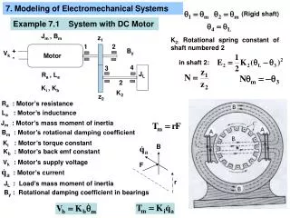
Electromechanical Systems Unit 2 AC Circuits 1 1
Aim and Learning Outcomes 2 • Most practical applications in electrical engineering involve alternating current and voltages. • This unit explains • analysis of AC circuits and their operations • use of capacitance transducers. • After completing this unit you should be able to • Analyse passive AC circuits comprising resistors, inductors and capacitors • To determine current flow, voltage distribution and power dissipation. • Identify series resonance. • Analyse power factor improvement circuits. • Describe the operation of capacitance transducers and their use in measuring displacement.
Content 3 • Introduction • Resistance Connected to an AC Supply • Inductance Connected to an AC Supply • Capacitance Connected to an AC Supply • Resistance and Inductance in Series with an AC Supply • Resistance and Capacitance in Series with an AC Supply • Resistance, Inductance and Capacitance in Series with an AC Supply • AC Supply in Parallel with Capacitance and with Inductance and Resistance in Series • Power Dissipation • Capacitance Transducers • Problems
Introduction OR • where • Vm = peak applied voltage in volts • f = supply frequency in Hz • t = time in seconds. 4 • Electricity supply systems are normally ac (alternating current). • The supply voltage varies sinusoidal • instantaneous applied voltage,
Resistance connected to an AC supply Instantaneous current, i Current and Voltage are in phase 5
Root Mean Square (rms) Voltage and Current “RMS value of an alternating current is that steady state current (dc) which when flowing through the given resistor for a given amount of time produces the same amount of heat as produced by the alternative current when flowing through the same resistance for the same time” 6 • The “effective” values of voltage and current over the whole cycle • rms voltage is • rms current is Meters normally indicate rms quantities and this value is equal to the DC value Other representations of Voltage or Current are • maximum or peak value • average value
Inductance connected to an AC supply i – instantaneous current i Phasor diagram and wave form Current lags Voltage by 90 degree rms current Using complex numbers and the j operator Inductive Reactance 7
Capacitance connected to an AC supply i Current leads Voltage by 90 degrees rms current Using complex numbers and the j operator Capacitance Reactance 8 Phasor diagram and wave form
R and L in series with an AC supply But and And Complex Impedance Cartesian Form 9 -j indicates that the current lags the voltage
Complex Impedance: Cartesian Form: In Polar Form phasor diagram constructed with RMS quantities -L indicates lagging current. Power factor, p.f. Complex impedance: 10
Exercise: For the circuit shown below, calculate the rms current I & phase angle L 11 Answer: I = 0.85A -32.10
R and C in series with an AC supply But and i but Complex Impedance The current, I in Cartesian form is given by +j signifies that the current leadsthe voltage. 12
Complex Impedance: I Cartesian form: In Polar Form phasor diagram drawn with RMS quantities +C identifies current leading voltage Power Factor 13 sinusoidal current leading the voltage
Exercise: For the circuit shown, calculate the rms current I & phase angle L 15 Answer: I = 5.32mA 57.90
RLC in series with an AC supply We know that: VC & But VL Complex Impedance VR 16
From previous page The phasor diagram (and hence the waveforms) depend on the relative values of L and 1/C. Three cases must be considered or 17
From previous page capacitive resistive inductive Resonant frequency 18
From previous page From the above equation for the current it is clear that the magnitude of the current varies with (and hence frequency, f). This variation is shown in the graph at o, = and they may be greater than V & • fo is called the series resonant frequency. • This phenomenon of series resonance is utilised in radio tuners. 19
Exercise: For circuit shown in figure, calculate the current and phase angle and power factor when frequency is (i) 159.2Hz, (ii) 1592.Hz and (iii) 503.3Hz How about you try this ? Answer: (i) 11.04 mA + 83.6o, 0.111 leading (ii) 11.04mA, -83.60, 0.111 lagging (iii) 100mA, 00, 1.0 (in phase) 20
AC Supply in Parallel with C, and in Series R &L Can U name the Laws? We know that: Substituting for the different Voltage components gives: and Hence, 21
Exercise: For the circuit shown calculate the minimum supply current, Is and the corresponding capacitance C. Frequency is 50 Hz. How about you try this one too? 22 Answer: ISmin = 3.71A C = 38.6F
Power Dissipation power dissipation | instantaneous = voltage| instantaneouscurrent | instantaneous We know that: Hence, instantaneous voltage, instantaneous current, but & net power transfer Therefore, 23
Real, Apparent and Reactive Power Im V P1 Re כ θ i P = Apparent power P1 = Real power P2 P2 = Reactive power P 24
Power Factor Correction Im V P1 Re O II I i P22 Pn P = Apparent power P1 = Real power P2 = Reactive power P2 P P22= New Reactive Power Pn= New Apparent Power I= Current to reduce Reactive Power 25
Capacitance Transducers • Displacement transducers are often variable capacitors, • Their capacitance varies with movement. • The value may be adjusted by varying either • the distance between the capacitance plates, or • the effective plate area, or • the effective dielectric between the plates Where 0 = permittivity of free space r = relative permittivity of dielectric A = area of overlap between the plates d = distance between the plates Capacitance 26
To determine the displacement by measuring the capacitance accurately. When the bridge is balanced, To achieve the maximum bridge sensitivity: • the two capacitors should be equal • the resistances equal to the capacitive reactance at the measuring frequency. For accurate measurements prevent or minimise:- • stray capacitance between leads and earth • transducer lead inductance • transducer dielectric losses • harmonic distortion (undesired components) in voltage supply 27
Linearity of the transducer may be improved by using a differentially connected displacement device The transducer is connected to adjacent arms of an ac bridge. Movement of the central plate increases the capacitance on one side and reduces it on the other. 28
Conclusion • AC supply with resistive load, RL in series, RC in series, RLC in series, and RLC in parallel. • Phasor & Cartesian representations. • Phase angle and power factor. • Dissipated Power. • Applications: Capacitance transducer 29
Problem Sheet Q1. A 20V 50Hz supply feeds a 20 Resistor in series with a 100mH inductor. Calculate the circuit (complex) impedance and current. Q2. A 200V supply feeds a series circuit comprising 250 resistor, 100mH inductor and a 159nF capacitor. Calculate the resonant frequency fo and the corresponding current. Also calculate the current when the frequency is:- fo/3 3fo Q3. A small company connected to 240V, 50Hz single-phase supply draws a current of 40A at 0.8 power factor lagging. A capacitance is connected across the supply to improve the power factor of the supply current to: i) unity ii) 0.95 lagging Calculate the supply current and capacitance in each case. Q4. The central plate of a differentially connected displacement transducer shown in Fig 2.10c is initially midway between the outer plates. Show that if the central plate is displaced d that the fractional change in the capacitances (C/C) is given approximately by: 30