Download
1 / 49
490 likes | 547 Views
Learn about the DRS4 waveform digitizing chip and its capabilities for high-speed sampling, high timing precision, low jitter, and deep sampling depth. Explore the design principles and solutions for fulfilling these requirements, as well as the advancements in the new generation of FADCs.

E N D
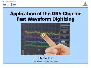
First results from the DRS4 waveform digitizing chip Stefan Ritt Paul Scherrer Institute, Switzerland
3 ps Timing with the DRS series ASICs Stefan Ritt Paul Scherrer Institute, Switzerland
Requirements High Sampling Speed SNR > 12 bit ps Timing Jitter High TemperatureStability Deep Sampling Depth Many Channels Picosecond Workshop, Lyon
A bit of history… MEG Experiment searching for me g down to 10-13 DRS1 2001 DRS2 2004 DRS3 2006 DRS4 2008 3000 Channels with GHz sampling Picosecond Workshop, Lyon
Design Principles How to fulfill all these needs?
The Domino Principle 0.2-2 ns Inverter “Domino” ring chain IN Waveform stored Out FADC 33 MHz Clock Shift Register “Time stretcher” GHz MHz Keep Domino wave running in a circular fashion and stop by trigger Domino Ring Sampler (DRS) Picosecond Workshop, Lyon
VDD’ t’ Origin of Jitter VDD/GND noise causes timing jitter! VDD R GND R VDD • Golden Rules: • Make R small Power Planes • Design for steep edges VDD/2 t Picosecond Workshop, Lyon
R C Example: Bus drivers • Sheet resistance M5: 0.036 W/sq., 4000mm x 0.4 mm 360 W • Area capacitance M5-M4: 0.037 fF/mm2+0.036fF/mm 0.35 pF Picosecond Workshop, Lyon
Bus driver simulation Picosecond Workshop, Lyon
Simulation Result 1 100 mV Picosecond Workshop, Lyon
Modified Bus Driver Picosecond Workshop, Lyon
Simulaiton Result 2 100 mV Picosecond Workshop, Lyon
More elaborate evaluation Timing-Jitter induced by power supply noise A. Strak, H. Tenhunen, http://www.strak.se/Adam_Strak_DCAS_2006.pdf Picosecond Workshop, Lyon
DRS4 X Rules for high precision timing • Keep local power supply stable • Low resistive power rails (planes) • Separate power supply for inverter chain + PLL from rest • Add on-chip decoupling capacitors • Try to keep number of simultaneously switching gates minimal • Design for fast transitions • Identify high load lines, driver them with enough power • Follow 1x 3x 10x 30x rule • Use differential signalling for critical lines • Inverter chain • Reference clock input • Do not use minimal transistors for critical paths Picosecond Workshop, Lyon
Solution: Clear before write write clear “Residual charge” problem R After sampling a pulse, some residual charge remains in the capacitors on the next turn and can mimic wrong pulses “Ghost pulse” 2% @ 2 GHz Picosecond Workshop, Lyon
ROI readout mode delayed trigger stop normal trigger stop after latency stop Trigger Delay 33 MHz e.g. 100 samples @ 33 MHz 3 us dead time(3.8 ns / sample @ 8 channels) readout shift register Patent pending! Picosecond Workshop, Lyon
readout Channel 0 1 Channel 0 1 0 1 Channel 1 Channel 1 Channel 2 Simultaneous Write/Read FPGA 0 Channel 0 0 Channel 1 8-foldanalog multi-eventbuffer Channel 2 0 Channel 3 0 Channel 4 0 Channel 5 0 Channel 6 0 Channel 7 0 Expected crosstalk ~few mV Picosecond Workshop, Lyon
G. Varner et al., Nucl.Instrum.Meth. A583, 447 (2007) Interleaved sampling 6 GSPS * 8 = 48 GSPS delays (167ps/8 = 21ps) Possible with DRS4 if delay is implemented on PCB Picosecond Workshop, Lyon
New generation of FADCs • 8 simultaneous flash ADCs on one chip • Requiredifferentialinput • DRS4 has beenredesigned withdifferentialoutput Picosecond Workshop, Lyon
DRS4 MUX Trigger an DAQ on same board • Using a multiplexer in DRS4, input signals can simultaneously digitized at 65 MHz and sampled in the DRS • FPGA can make local trigger(or global one) and stop DRSupon a trigger • DRS readout (5 GHz samples)though same 8-channel FADCs global trigger bus trigger FPGA DRS FADC12 bit 65 MHz analog front end LVDS SRAM “Free” local trigger capability without additional hardware Picosecond Workshop, Lyon
Decisions • Usage of external ADC • Analog Devices has better engineers • Get information faster off-chip (1 sample in 30 ns, 12 bits would need 400 MHz clock) • Possibility for continuous sampling ( triggering) • Use passive input • Hard to design 1 GHz buffer in 0.25 mm technology, needed for 1V linear range • Lower power consumption • Problem: Bond wire Cparasitic limits bandwidth, high input current 0.8 mA • Use Gate-All-Around (GAA) transistors • Radiation hardness • Good W/L vs. chip area bigger gates reduced mismatch • On-chip PLL for sampling frequency stabilization • Flexible channel configuration Picosecond Workshop, Lyon
DRS4 Have we achieved the requirements?
DRS4 • Fabricated in 0.25 mm 1P5M MMC process(UMC), 5 x 5 mm2, radiation hard • 8+1 ch. each 1024 bins,4 ch. 2048, …, 1 ch. 8192 • Differential inputs/outputs • Sampling speed 500 MHz … 6 GHz • On-chip PLL stabilization • Readout speed 30 MHz, multiplexedor in parallel Picosecond Workshop, Lyon
DRS4 packaging DRS4 flip-chip DRS4 DRS3 4.2 mm 9 mm 18 mm Picosecond Workshop, Lyon
On-chip PLL Simulation loop filter DRS4 Vspeed Phase detector up down Measurement Reference Clockfclk = fsamp / 2048 • PLL jitter « 100 ps (Spartan-3 jitter 150 ps) • “Dead Band” free • Does not lock on higher harmonics Picosecond Workshop, Lyon
Linear Range (DRS3) • Excellent linearity from 0.1V … 1.1V @ 33 MHz readout 0.5 mV max. Picosecond Workshop, Lyon
QFP package 850 MHz (-3dB) Measurement Bandwidth • Bandwidth is determined by bond wire and internalbus resistance/capacitance: • 850 MHz (QFP), 950 MHz (QFN), ??? (flip-chip) finalbus width Simulation Picosecond Workshop, Lyon
Signal-to-noise ratio (DRS3!) • “Fixed pattern” offset error of 5 mV RMScan be reduced to 0.35 mV by offsetcorrection in FPGA • SNR: • 1 V linear range / 0.35 mV = 69 dB (11.5 bits) Offset Correction Picosecond Workshop, Lyon
Timing jitter • Inverter chain has transistor variations Dti between samples differ “Fixed pattern jitter” • “Differential temporal nonlinearity” TDi= Dti – Dtnominal • “Integral temporal nonlinearity”TIi = SDti – iDtnominal • “Random jitter” = variation of Dti between measurements Dt1 Dt2 Dt3 Dt4 Dt5 TD1 TI5 Picosecond Workshop, Lyon
Fixed jitter calibration • Fixed jitter is constant over time, can be measured and corrected for • Several methods are commonly used • Most use sine wave with random phase and correct for TDi on a statistical basis Picosecond Workshop, Lyon
Sine Curve Fit Method i yji : i-th sample of measurement j aj fj ajoj : sine wave parameters bi : phase error fixed jitter • “Iterative global fit”: • Determine rough sine wave parameters for each measurement by fit • Determine bi using all measurements where sample “i” is near zero crossing • Make several iterations j S. Lehner, B. Keil, PSI Picosecond Workshop, Lyon
Fixed Pattern Jitter Results • TDi typically ~50 ps RMS @ 5 GHz • TIi goes up to ~600 ps • Inter-channel variation on same chip is very small since all channels are driven by the same domino wave Picosecond Workshop, Lyon
Random Jitter Results • Sine curve frequency fitted for each measurement (PLL jitter compensation) • Encouraging result for DRS3:2.7 ps RMS (best channel)3.9 ps RMS (worst channel)phase error in fitting sine wave • Differential measurement t1 – t2 adds a 2, needs to be verified by measurement • Measurement of n points on a rising edge of a signal improves by n Measurements for DRS4 currently going on, expected to be slightly better Picosecond Workshop, Lyon
Inter-Chip Synchronization Chip 1 Trigger t1 ReferenceClock Chip 2 t2 PLL Jitter? Picosecond Workshop, Lyon
Domino + PLL Reference Clock 8 inputs Global Sine Wave Shift register Rules for Synchronization • Synchronize chips with a global low jitter reference clock • Determine timing of a hit in respect to global clock (beginning of sampling window) • PLL timing jitter < desired accuracy you’re done • PLL timing jitter > desired accuracy use clock channel with sine ~100 ps jitter few ps accuracy Picosecond Workshop, Lyon
Chip Comparison Picosecond Workshop, Lyon
Experiments using DRS chip MEG 3000 channels DRS2 MAGIC-II 400 channels DRS2 BPM for XFEL@PSI 1000 channels DRS4 (planned) MACE (India) 400 channels DRS4 (planned) Picosecond Workshop, Lyon
32-channel 65 MHz/12bit digitizer “boosted” by DRS4 chip to 5 GHz Availability • DRS4 will become available in larger quantities in November 2008 • Chip can be obtained from PSI on a “non-profit” basis • Delivery “as-is” • Reference design (schematics) from PSI • Costs ~ 10-15$/channel • Costs decrease if we find sell more… • VME boards from industry in 2009 ext. Trigger Input DRS4 USB 2.0 Picosecond Workshop, Lyon
Datasheet Picosecond Workshop, Lyon
Conclusions • Fast waveform digitizing is in my opinion the best choiceto achieve ps timing • Phase noise of a single cell using a 500 MHz sine wave has been measured to be 3-4 ps in the DRS chip • More characterization is needed from community (Single pulse response, 48 GHz mode, …) DRS4 has prospects to come quite a step closer to our goal http://midas.psi.ch/drs Picosecond Workshop, Lyon
0 0 0 0 0 0 1 0 0 0 0 0 0 0 0 0 0 0 0 0 0 0 1 0 0 1 0 0 0 0 0 0 0 0 0 0 0 0 0 0 0 0 0 0 1 0 0 0 Simple inverter chain 0 0 0 0 0 0 1 0 0 0 0 0 0 0 0 0 0 0 1 1 1 1 1 0 0 1 1 1 1 1 1 1 1 1 1 1 1 1 1 1 1 1 0 0 0 1 1 1 Picosecond Workshop, Lyon
Design of Inverter Chain PMOS > NMOS PMOS < NMOS Picosecond Workshop, Lyon
“Tail Biting” speed enable 1 2 3 4 1 2 3 4 Picosecond Workshop, Lyon
Stopping speed enable 1 2 3 4 enable 1 2 3 4 time Picosecond Workshop, Lyon
Stop Schematics WE 1 2 WE 3 D Q D Q D Q RES RES RES 2 3 1 Picosecond Workshop, Lyon
Complete Domino Cells Domino Cell 1 Domino Cell 2 Domino Cell 3 Vspeed Enable Write D D D Q Q Q RES RES RES Start Sampling Cell 1 Sampling Cell 2 Sampling Cell 3 Picosecond Workshop, Lyon
On-line waveform display S848 PMTs “virtual oscilloscope” template fit click pedestal histo Picosecond Workshop, Lyon
Constant Fraction Discr. Delayed signal Inverted signal Sum Clock 12 bit Latch Latch Latch Latch + Latch Latch S + <0 & MULT 0 Picosecond Workshop, Lyon