Download
1 / 21
210 likes | 403 Views
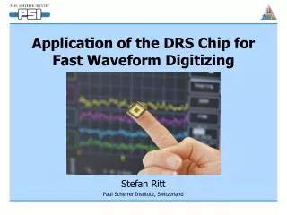
The DRS2 Chip: A 4.5 GHz Waveform Digitizing Chip for the MEG Experiment. Stefan Ritt Paul Scherrer Institute, Switzerland. Kinematics. q e g = 180°. g. e. m. E e = 52.8 MeV. E g = 52.8 MeV. The MEG Experiment at PSI. Goal: m → e g at 10 -13.

E N D
The DRS2 Chip: A 4.5 GHz Waveform Digitizing Chip for the MEG Experiment Stefan Ritt Paul Scherrer Institute, Switzerland
Kinematics qeg= 180° g e m Ee = 52.8 MeV Eg = 52.8 MeV The MEG Experiment at PSI Goal: m → eg at 10-13 • Stopped m beam of 107-108 s-1, 100% duty factor • Liquid Xe calorimeter for g detection • Solenoidal magnetic spectrometer • Radial drift chambers for e+ momentum determination • Timing counter for e+ Planning R & D Assmbl. Data Taking N7-4 T. Iawamoto 97 98 99 00 01 02 03 04 05 06 07 IEEE/NSS Rome 2004
PMT sum 0.511 MeV 51.5 MeV t ~100ns Waveform Digitizing • Needed: • Pile-up rejection (BG from 108 µ decays in unsegmented calorimeter) • ADC dynamic range of 12 bit • TDC resolution of 40 ps • Analog pipeline (L1 trigger) ~300ns • 3000 channels 2 GS 10 Bit 100€/Chn IEEE/NSS Rome 2004
The DRS chip: principle of operation Domino Ring Sampler IEEE/NSS Rome 2004
Design of Inverter Chain PMOS > NMOS PMOS < NMOS IEEE/NSS Rome 2004
“Tail Biting” enable 1 2 3 4 1 2 3 4 IEEE/NSS Rome 2004
Domino Speed Control UR US UR US • Two independent voltages to control domino wave speed • UR used to select speed range • Us used for fine-adjustment • Need to compensate temperature and Vdd drifts IEEE/NSS Rome 2004
Current mode readout • First implemented in DRS2 (DRS1 had charge readout) • Sampled charge does not leave chip • Current readout less sensitive to charge injection and cross-talk R (700 ) I Vin Vout read write . . . C (200fF) IEEE/NSS Rome 2004
Timing Reference domino wave signal 20 MHz Reference clock 8 inputs PMT hit shift register Domino stops after trigger latency Reference clock MUX • Domino speed stability of 10-3 : • 400 ps uncertainty for full window • 25 ps uncertainty for timing relative to edge IEEE/NSS Rome 2004
Fabricated in 0.25 mm 1P5M MMC process (UMC), 5 x 5 mm2 Radiation Hard (CMS Pixel library, R. Horisberger) 10 channels (8 data + 2 calibration), each 1024 bins (300 ns analog delay + 100 ns signal at 2.5 GHz) Maximal sampling speed 4.5 GHz Readout speed 40 MHz Submitted to UMC in November 2003, 58 chips (400 channels) received in March 2004 Packaged chip costs: 35 € / chn. (MPW run) 3 € / chn. (engineering run) The DRS2 Chip Readout Shift Register Domino Circuit 10 channels x 1024 bins IEEE/NSS Rome 2004
DRS2 Test Results Preliminary !
Measured DRS2 Parameters • Linear response up to 400mV • Usable range of 1V p-p • Speed range 0.5 GHz – 4.2 GHz Linear approximation IEEE/NSS Rome 2004
Domino Wave Pulse Reference Clock ~200 psec PLL Stabilization • Unstabilized jitter: ~70ps / turn • Temperature coefficient: 500ps / ºC PLL Vspeed • R. Paoletti, N. Turini, R. Pegna • MAGIC collaboration External Common Reference Clock (1-4 MHz) IEEE/NSS Rome 2004
Frequency stabilization • Compensate for temperature drifts • Change Vspeed only between events, keep stable during acquisition phase • Jitter ~ 150ps • Timing accuracy with 9th channel < 25ps 150ps Vspeed FPGA Frequency Counter 16-bit DAC LUT IEEE/NSS Rome 2004
Estimated Bandwidth Direct DRS2 output • Input pulse rising time: 0.9 ns • Sampled at 2.5 GHz: 0.4 ns / sample • Reconstructed rise time: 3 samples → 1.2 ns • Estimated BW » 500 MHz • Limited by protection diodes 40 MHz readout clock IEEE/NSS Rome 2004
DAQ Boards R. Paoletti, N. Turini, R. Pegna MAGIC collaboration PSI GVME Board FPGA with 4 Power-PC DRS USB IEEE/NSS Rome 2004
Pulses are nicely reproduced • Analog inputs not properly terminated • Non-constant response over 1024 cells (parasitic R of current readout on chip) mV ns Digitized Signals • 7 ns pulses 500 mV • Digitized at 2.5 GHz with USB test board IEEE/NSS Rome 2004
Signal-to-noise ratio • 1 V DC input signal, common mode subtracted • Individual bin has RMS of 2 mV → SNR = 500:1 (9 bit) • Integration over 100 ns PMT pulse (250 bins) has RMS of0.16 mV → SNR = 6200:1 (12.6 bit) • Could be improved by better analog design of Mezzanine board mV mV IEEE/NSS Rome 2004
Waveform Analysis pb Experiment 500 MHz sampling • MEG: 3000 channels, 100 Hz, 1024 samples → 600 MB/sec • Compress “interesting” and pile-up events in FPGA (→ 10x) • Fit “background” events in PC farm (~10 PCs) with individual PMT response functions, derive multi-hit ADC and TDC data • Overall data rate ~2 MB/sec IEEE/NSS Rome 2004
Next generation: DRS3 ? IEEE/NSS Rome 2004
Conclusions • Successful design of DRS2 with 8 x 1024 bins, running at 4.5 GHz • Deploy ~200 channels in MEG Experiment in spring 2005 • Use DRS2 for drift chamber readout • Final version (DRS3, 3000 channels) in 2006 • Not specific to MEG, useful for other experiments IEEE/NSS Rome 2004