First results from QUIET
First results from QUIET. Osamu Tajima (KEK) The QUIET Collaboration. B-modes have NOT been observed yet ! . QUIET aims to detect B-modes from ground !. B-modes power. Direct limits : r < 0.7 (ground experiment). Indirect limits: r < 0.2. Primordial B-modes. Contribution from

First results from QUIET
E N D
Presentation Transcript
First results from QUIET Osamu Tajima (KEK) The QUIET Collaboration
B-modes have NOT been observed yet ! QUIET aims to detect B-modes from ground ! B-modes power Direct limits : r < 0.7 (ground experiment) Indirect limits: r < 0.2 Primordial B-modes Contribution from Gravitational lensing Multipolel (=180o/q) Large scale Small scale Angular Scale q
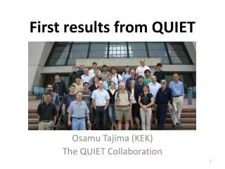
The QUIET Collaboration 5 countries, 14 institutes, ~35 scientists Chajnantor Plateau (5,080m) Chile Atacama Desert World’s best site for observation frequencies of QUIET !
Observation Patches ~20o 4 CMB patches were chosen (~3% of full sky) Observing them DEEPLY (Galaxy observation when CMB patches are not visible) Map precision on 1°x1°: ~1μK (7.5 months at 43GHz)
CMB QUIET Telescope CMB 90 detectors array for 95 GHz Receiver ( detector array inside) ~30cm
QUIET observation time at Chajnantor, 5,080m ~30cm ~30cm > 11,000 H 19 detectors at 43GHz array sensitivity 69uKs1/2 90 detectors at 95GHz array sensitivity ~70uKs1/2 7.5 months 1.5 years
What’s important towards B-mode detection ? B-mode ~ 1/100 of E-modes x100 better sensitivity than past experiments • Detector array: High sensitive instrument • limitation of single detector sensitivity • Several hundreds ~ thousand detectors • several (past) ~100 (Now) ~1000 (Future) • Good systematic error control for instrument • Understanding of Foregrounds QUIET : intermediate stage (2008-2010) - Observation with 90 (19) detectors at 95GHz (43GHz) - One of the best B-modes search to date - Proof of technology for future
Foregrounds and observation bands QUIET Other experiments using bolometer 95 GHz 43 GHz B-mode (as QUIET-1 limits) QUIET 43GHz data is very important to understand the contribution of Synchrotron emission
Impact of systematic error In case of 1% precision of calibrations … Temperature anisotropy spurious pol. 1% of I to Q/U E-modes 2o for pol. angle l(l+1)Cl /2p (uK2) lensing B-modes r = 0.10 r = 0.01 Multipolel (=180o/q) Have to minimize spurious polarization < 1% Have to achieve < 2o precision
Robust detector against to the systematic biases QUIET polarization detector array CMB 90 detector array for 95 GHz Septum Polarizer Polarization Sensor Module Array sensitivity ~70 uKs1/2 3cm
Septum Polarizer (OMT) Input Output L R Output y R =EX-iEY Input L =EX+iEY x
Polarization Sensor Module Septum polarizer R L Antenna to pick up “L”, “R” HEMT amp. GB GA Phase switch modulation at 4kHz & 50Hz ±1 1 180 Coupler (±1) -Q +Q 90 Coupler (±i) W-band module +U -U
Polarization Sensor Module Septum polarizer R L Simultaneous measurement of Stokes Q and U HEMT amp. GB GA Polarization (Q, U) aGAxGB Phase switch modulation at 4kHz & 50Hz ±1 1 Strong immunity from systematic bias NO spurious polarization, NO polarization angle rotation, i.e. Q/U rotation, even though there is gain fluctuation 180 Coupler (±1) -Q +Q QUIET detector is extremely stable for the polarization response 90 Coupler (±i) +U -U
Instrumental spurious polarization I Q/U Leakage CMB Caused by cross talk in septum polarizer NO time variation because it caused by waveguides components Septum Polarizer Elevation nods Polarization Sensor Module Spurious polarization DQ DI Variation of atmosphere thickness 43GHz receiver IQ : 1.0% IU : 0.2% (precision 0.1%) 95GHz receiver IQ : < 0.5% IU : < 0.5% average 0.6% ~ ~
Calibration for Polarization (43GHz receiver) by Y. Chinone ~4 min scan time for each Taurus Crab nebula (TauA) Rotate parallactic angle with keeping the line of sight Q Q TQ(U) cos(2(q-g)) Dgabsolute = 1.7° Catalog uncertainty for polarization angle 1.5° at 43GHz (WMAP) 0.2° at 95GHz (IRAM) U QUIET telescope θ
What’s important towards B-mode detection ? B-mode ~ 1/100 of E-modes x100 better sensitivity than past experiments • Detector array: High sensitive instrument • limitation of single detector sensitivity • Several hundreds ~ thousand detectors • several (past) ~100 (Now) ~1000 (Future) • Good systematic error control for instrument • Understanding of Foregrounds Intermediate stage Robust coherent detector Calibration, Scan strategy Analysis method 43GHz receiver for Synchrotron emission Verified with first results
End-Analysis Strategy Data Selection Filter / Map Making Validation Tests Power Spectra Cosmological Parameters
End-Analysis Strategy Data Selection Blind Analysis Framework Calibrations Filter / Map Making Systematic Error Check Validation Tests “Box Open” Un-blinding the results - after passing validation tests - after confirmation of syst. errors Power Spectra Cosmological Parameters
Data Selection- way to control hidden systematic bias - Time-ordered-data for polarization response Extremely bad weather Contaminated Selection Criteria 80 mK Data Set Good weather Clean 0.1 mK To determine the selection criteria, we need the way to evaluate such hidden bias
Analysis Validation : Null Tests Way to evaluate the hidden bias in data without looking at the results MC MC MC – (S + N2) (N1 – N2) (S + N1) Same CMB signal but different noise, contaminations QU diodes diff. We performed null tests with various subdivisions (42 different ways). - weather condition - cryostat temperature - … We determined selection criteria with feed-back from null tests 69.4% for 43 GHz detector array
Evaluation of Null Spectra w/ Cross-correlation w/o Cross-correlation Auto-correlation Significant non-null bias (20% of statistical error) • MC w/o any • contamination = Cl / sl Bias estimator : There is significant bias even if the criteria are tighten (auto-correlation) It indicates that faint contamination was always exists in the data Need the way to drop such effect with keeping the CMB signal
Cross-correlation Technique to eliminate the noise and remaining contamination Maps of different time periods Cross-correlationswith all the combinations <(Sl + N1l ) (Sl + N2l )> + <(Sl + N1l ) (Sl + N2l )> + <(Sl + N2l ) (Sl + N3l )> Sl + N1l Sl + N2l <Sl2> Sl + N3l CMB signals (Sl) are the same and correlations do not vanish, whilenoise terms (Nl) have no correlations <NilNjl> = 0.
There were “far-sidelobes” during 43GHz observation season Upper part of ground screen was missing during 43GHz observation 95GHz observation <-60dB of Main beam 43GHz observation From Y. Chinone’s thesis. This problem was well characterized by him. Contaminations by far-sidelobes were always existed, e.g. picking up ground structure
Way to divide the data towardsground structure elimination + 6 different deck angles
Elimination of residual biaswith cross-correlation w/ Cross-correlation w/o Cross-correlation Auto-correlation Significant non-null bias (20% of statistical error) • MC w/o any • contamination = Cl / sl Bias estimator : There is significant bias even if the criteria are tighten (auto-correlation) It indicates that faint contamination was always exists in the data Cross-correlation eliminates such residual bias with keeping the CMB signal
E-modes Significant power is detected at 1st , 2nd peak region Consistent with LCDM model QUIET / LCDM = 0.87 ± 0.10 PTE from LCDM 14% for EE + BB + EB
B-modes : r < 2.2 @95%CL(zero-consistent : r=0.35+1.06-0.87) Second best upper limits wheres short observation time Limits from QUIET 43GHz (7.5 months ~1/3 of BICEP-1 data) Expected limits with 95GHz data Expected Limits in QUIET-2 w/ 500 detectors Predictions from major models ( = 180o/q) We have achieved least systematic errors to date (next page) Good prospects to achieve O(r=0.01) with upgrade
Least systematic errors to date IQ/U leakage effect • Extensive study of systematic errors • Least systematic error reported to date • Strong proof of our technology for future • Good prospects for reduction of systematic errors with 95GHz data Polarization angle uncertainty Possible residual effects induced by “far-sidelobes” They had been improved for 95GHz receiver
Detection of Foreground E-modes B-modes
Foreground detection in CMB-1 patch WMAP K-band QK cross-corr. QUIET Q-band (~1/3 of EE from LCDM) EE BB One of four patches (CMB-1) at 1stbin (l=25–75) b= –3.1 for extrapolation r = 0.02 Consistent with synchrotron emission It does not dominate 95GHz region unless we reach r~0.02 We confirmed “foreground receiver” at 43GHz is useful for the evaluation of foreground
Summary Three important items toward B-mode detection • Detector array: High sensitive instrument • Several hundreds ~ thousand detectors • QUIET demonstrates strong proof of the technology with 19 (43GHz) and 90 (95GHz) detectors • Good systematic error control for instrument • QUIET established robust analysis method • Least systematic errors to date • To be better systematic errors with 95GHz data • Understanding of Foregrounds • Detection of synchrotron emission at 43GHz • one of four CMB patches • It does not dominate 95GHz region unless we reach r~0.02 • We confirmed “foreground receiver” is useful
Another Advantage of QUIET module Noise spectra for 95 GHz polarimeter No modulation Modulation frequency by telescope scan Moduleation with 4kHz phase switch Additional modulation with 50Hz phase switch 1/f knee frequency << scan frequency
Another Advantage of QUIET’s module QUIET’s sensitive region Limited by beam resolution Limited by scan range by Y. Chinone NOsensitivity degradationdue to 1/f noise
TOD filtering • Azimuth domain filtering • Knee frequency fknee(~5.5mHz) << fscan • Highpass cutoff around scan frequency with little loss of sensitivity • Sufficient for both 1/f noise and atmosphere • Grand structure subtraction Naïve N-1 filter Our filter Scan
QUIET’s Constant Elevation Scan Constant Elevation Constant atmosphere emission Therefore, C.E.S minimizes the effect of atmosphere emission
QUIET’s daily scans for the CMB-patch Trace the patch with ~20o elevation step ~20o ~1.5 hours scans at each elevation
Natural sky rotation due to the earth rotation CMB polarization rotates with sky rotation Spurious polarization bias does not rotate ! CMB polarization Leakage bias is smeared by natural sky rotation Spurious polarization induced by CMB temperature anisotropy and I to Q/U leakage
We smeared residual spurious polarizationwith weekly boresight rotation Observation with various “deck” rotation by M. Hasegawa