Download
1 / 22
220 likes | 368 Views
many. Design and Performance of the 5 GHz Waveform Digitizing Chip DRS3 for the MEG Experiment. Stefan Ritt Paul Scherrer Institute, Switzerland. Trends in DAQ. Higher event rates pile-up Baseline estimation event-by-event removal of 60 Hz noise

E N D
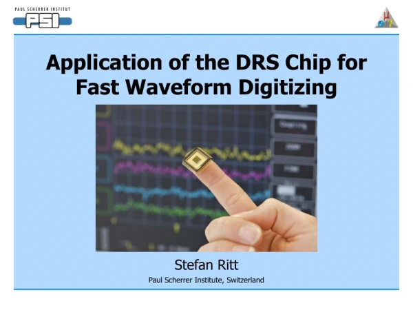
many Design and Performance of the 5 GHz Waveform Digitizing Chip DRS3 for the MEG Experiment Stefan Ritt Paul Scherrer Institute, Switzerland
Trends in DAQ • Higher event rates pile-up • Baseline estimation event-by-event removal of 60 Hz noise • Particle identification by signal shape from PMTs • Usage of FADCs instead of ADCs/Discriminators/TDCs • Problems: • expensive • high power requirement • low density hits Moving average baseline IEEE/NSS Honolulu 2007
Switched Capacitor Array 0.2-2 ns Inverter “Domino” ring chain IN Waveform stored Out FADC 33 MHz Clock Shift Register “Time stretcher” GHz MHz Keep Domino wave running in a circular fashion and stop by trigger Domino Ring Sampler (DRS) IEEE/NSS Honolulu 2007
Linear inverter chain causes non-linearity Folded Layout IEEE/NSS Honolulu 2007
0 0 0 0 0 0 1 0 0 0 0 0 0 0 0 0 0 0 0 0 0 0 1 0 0 1 0 0 0 0 0 0 0 0 0 0 0 0 0 0 0 0 0 0 1 0 0 0 Simple inverter chain 0 0 0 0 0 0 1 0 0 0 0 0 0 0 0 0 0 0 1 1 1 1 1 0 0 1 1 1 1 1 1 1 1 1 1 1 1 1 1 1 1 1 0 0 0 1 1 1 IEEE/NSS Honolulu 2007
Design of Inverter Chain PMOS > NMOS PMOS < NMOS IEEE/NSS Honolulu 2007
“Tail Biting” speed enable 1 2 3 4 1 2 3 4 IEEE/NSS Honolulu 2007
Stopping speed enable 1 2 3 4 enable 1 2 3 4 time IEEE/NSS Honolulu 2007
Stop Schematics WE 1 2 WE 3 D Q D Q D Q RES RES RES 2 3 1 IEEE/NSS Honolulu 2007
I DRS2 DRS3 Sample readout DRS1 Tiny signal 20 pF 0.2 pF Temperature Dependence ~kT IEEE/NSS Honolulu 2007
ROI readout mode delayed trigger stop normal trigger stop after latency stop Trigger Delay 33 MHz e.g. 100 samples @ 33 MHz 3 us dead time(2.5 ns / sample @ 12 channels) readout shift register Patent pending! IEEE/NSS Honolulu 2007
DRS3 • Fabricated in 0.25 mm 1P5M MMC process(UMC), 5 x 5 mm2, radiation hard • 12 ch. each 1024 bins,6 ch. 2048, …, 1 ch. 12288 • Sampling speed 10 MHz … 5 GHz • Readout speed 33 MHz, multiplexedor in parallel • 50 prototypes receivedin July ‘06 IEEE/NSS Honolulu 2007
Sampling speed • Unstabilized jitter: ~70ps / turn • Temperature coefficient: 500ps / ºC ~200 psec Vspeed PLL Reference Clock (1-4 MHz) R. Paoletti, N. Turini, R. Pegna, MAGIC collaboration IEEE/NSS Honolulu 2007
Bandwidth + Linearity • Readout chain shows excellent linearity from 0.1V … 1.1V @ 33 MHz reaout • Analog Bandwidth is currently limited by high resistance of on-chip signal bus, will be increased significantly with DRS4 0.5 mV max. 450 MHz (-3dB) IEEE/NSS Honolulu 2007
Signal-to-noise ratio • “Fixed pattern” offset error of 5 mV RMScan be reduced to 0.35 mV by offsetcorrection in FPGA • SNR: • 1 V linear range / 0.35 mV = 69 dB (11.5 bits) Offset Correction IEEE/NSS Honolulu 2007
Solution: Clear before write write clear “Residual charge” problem R After sampling a pulse, some residual charge remains in the capacitors on the next turn and can mimic wrong pulses “Ghost pulse” 2% @ 2 GHz IEEE/NSS Honolulu 2007
VPC & USB boards USB interfaceboard DRS3 32 channels input 14-bit flash ADCAD9248 DRS2 PSI general purposeVME board with 2 PPC cores IEEE/NSS Honolulu 2007
Availability 32-channel 65 MHz/12bit digitizer “boosted” by DRS4 chip to 5 GHz trigger FPGA DRS FADC12 bit 65 MHz analog front end MUX LVDS SRAM IEEE/NSS Honolulu 2007
Conclusions • 3000 Channels with DRS2 chip run-ning in MEG experiment since 2006 • The DRS3 chip solves temperature dependence of DRS2 chip, DRS4 solves ghost pulse problem • The DRS4 chip will be available in larger quantities beginning 2008 http://midas.psi.ch/drs IEEE/NSS Honolulu 2007
Complete Domino Cells Domino Cell 1 Domino Cell 2 Domino Cell 3 Vspeed Enable Write D D D Q Q Q RES RES RES Start Sampling Cell 1 Sampling Cell 2 Sampling Cell 3 IEEE/NSS Honolulu 2007