Download
1 / 23
230 likes | 326 Views
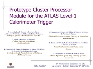
Consideration of the LAr LDPS for the MM Trigger Processor. Kenneth Johns University of Arizona Block diagrams and some slides are edited from those of Guy Perrot (LAPP). Overview.

E N D
Consideration of the LAr LDPS for the MM Trigger Processor Kenneth Johns University of Arizona Block diagrams and some slides are edited from those of Guy Perrot (LAPP)
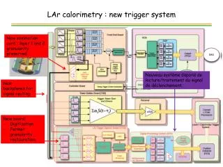
Overview • The LAr Calorimeter upgrade reduces the L1 EM object trigger rates by using finer granularity information (SuperCells versus Towers) as input to the L1 Calo Trigger system • Exploits differences in shower shape between signal and background • Data flow • SuperCell signals are digitized on-detector at 40 MHz (320 SC per LTDB (LAr Trigger Digitizer Board) • Data is optically transmitted to the Back-end electronics at 5.12 Gbps (using the LOCx2 and LOCld) • There, the ADC data is converted to energy and time and sent to the L1 Calo Trigger System and TDAQ using the LDPS (LAr Digital Processing System)
LAr to Muon Dictionary • LTDB = ADDC • LAr Trigger Digitizer Board = ART Data Driver Card • LOCx2+LOCld = GBT • LDPS = MM Trigger Processor • LAr Digital Processing System = MM Trigger Processor
MM Trigger Processor L1 Muon Sector Logic @ 40 MHz Data Monitoring PCs 10/40GbE via fabric ADDC (ART Data Driver Cards) MM Trigger Processor Blades Busy FELIX DCS ART Data @ 40 MHz TTC GBT Links Via Zone 3 ROS PCs TDAQ MM Trigger Processor programming, configuration, monitoring To HLT Configuration & Monitoring Partition Master PC ATCA System Manager To shelf managers and Base interface (GbE) FELIX GBT Links DCS ADDC Config & Monitoring ADDC configuration and monitoring, TTC BE TTC Partition FE TTC
LAr and Muon Backend I/O • LAr LDPS blade • Input: 40 (48) x 4 optical fibers at 5.12 Gbps • Output: 40 (48) x 4 optical fibers at ~10+ Gbps to L1 Calo • Output: Input data and results to TDAQ • Output: Input data and results to private Monitor PCs • MM Trigger blade • Input: 32 (36) x 4 optical fibers at 4.48 Gbps (Wide Bus mode) • Output: 1 x 4 optical fibers at 4.48? Gbps • Output: Input data and results to TDAQ • Output: ?? Input data and results to private Monitor PCs
MM Trigger Processor Communications • ADDC to AMC data flow • AMC to Muon Sector Logic data flow • GbE Base Interface • Board Configuration • Board Monitoring • Histogramming • 10GbE Fabric interface • Data monitoring (Fast) • GBT links • TTC/Busy • TDAQ Data • JTAG • IPM Bus • Only ATCA management! • Power
MM Trigger Processor 1 GBT JTAG JTAG Muon SectorLogic Data @ 40 MHz AMC JTAG µ POD Tx (x4) JTAG 1 48 I2C 1Tx links 1 GbE FPGA (DSP SOC) Sensors FELIX GBT Up to 4 GBT connectors 4 Zone 3: RTM TTC (ATLAS Event-TDAQ) (TTC) µ POD Rx (x4) Ref Clks (TTC, XAUI…) 48 4 ADDC Data @ 40 MHz 4 32 Rx links XAUI 10Gbps (PCIe?) GbE GBT GbE (Debugging) IPML,JTAG,RefClks… RJ45 MMC GBT 4 1 FPGA 1 Ch1 10GbE GBT AMC Muon SectorLogic Data @ 40 MHz µ POD Tx (x4) XAUI (PCIe?) 1 48 1Tx links 16 4 1 GbE FPGA (DSP SOC) 4 ATCA Switches TTC 16 µ POD Rx (x4) 4 ADDC Data @ 40 MHz 48 (Data Monitoring) Zone 2 : Fabric 32 Rx links 4 TTC XAUI 10Gbps (PCIe?) Ch2 10GbE IPML,JTAG,RefClks… 10GbE MMC 1 GBT AMC 1 GbE Muon SectorLogic Data @ 40 MHz µ POD Tx (x4) 1GbE 1 1 48 1Tx links 1 GbE 4 FPGA (DSP SOC) 1 4 Ch1 1GbE TTC 1 ADDC Data @ 40 MHz 1/10 GbE Switch µ POD Rx (x4) 4 1 GbE 48 32 Rx links XAUI 10Gbps (PCIe?) ATCA Switches 4 1 Zone 2 : Base (AMC Reprogramming, AMC Configuration, AMC Monitoring) IPML,JTAG,RefClks… MMC Ch2 1GbE 1 GBT I2C AMC IPML, JTAG, I2C Muon SectorLogic Data @ 40 MHz µ POD Tx (x4) 1 10/100MbE 48 1Tx links 1 GbE FPGA (DSP SOC) 1 4 TTC ATCA Shelf Manager I2C IPMB IPMC µ POD Rx (x4) ATCA Power 400W ADDC Data @ 40 MHz 48 4 32 Rx links (ATCA Management, Monitoring) XAUI 10Gbps (PCIe?) Zone 1 IPML,JTAG,RefClks… MMC ATCA Shelf Power 48V Power
MM Trigger Processor Communications • ADDC to AMC data flow • AMC to Muon Sector Logic data flow • GbE Base Interface • Board Configuration • Board Monitoring • Histogramming • 10GbE Fabric interface • Data monitoring (Fast) • GBT links • TTC/Busy • TDAQ Data • JTAG • IPM Bus • Only ATCA management! • Power
AMC Demonstrator Status • Design (Stony Brook) and layout (BNL) are complete • Fabricated AMC board expected before 12/1 • All parts in hand except MicroPOD optics, optical cables, 40 MHz clock and front panels • Firmware support (Arizona) in progress • Perhaps available to users May 2014 • Longer term, LAPP holds responsibility for ATLAS AMC design and production • Unclear if LAPP design will follow AMC Demonstrator design
AMC Carrier Card Status • Carrier demonstrator cards (including IPMC) with Altera FPGA have been produced by LAPP and will be made available to Stony Brook and Arizona soon • LAPP Carrier demonstrator card design currently being translated into Stony Brook PCB design software • Stony Brook will design a second Carrier card demonstrator with a GbE switch and increased power for AMC slots • Perhaps available May 2014 • Longer term, Stony Brook, BNL, Arizona hold responsibility for ATLAS Carrier design, production and firmware
AMC Parts Layout (top) DDR3 RAM chips Xilinx Vertex-7 4 micro-POD arrays 2x12 receivers and 2x12 transmitters each
AMC Parts Layout (bottom) Clock chips
AMC Routing (top layer) • 16 layers total with thru vias • Material N4000-13EP
Conclusions • The LAr LDPS is a developed candidate for the MM Trigger Processor • Pros • Takes advantage of an existing R&D program to develop AMC cards using high density AvagoMicroPODs and FPGAs for Serdes and supporting Carrier cards • Though not final, data paths are defined for TDAQ, TTC, configuration, monitoring, etc. • AMC and Carrier card demonstrators well along and both AMC and Carrier cards will be available for users by May 2014 • Cons • Output fibers for Muon Sector Logic << Output fibers for L1 Calo trigger • Monitor stream (10 GbE out) probably overkill • Unknown compatibility with sTGC Trigger Processor
LAr LDPS L1 Calo Data @ 40 MHz Data Monitoring PCs 10/40GbE via fabric LTDBs LDPBs Busy GBT Links Via Zone 3 FELIX DCS ADC Data @ 40 MHz TTC ROS PCs TDAQ LDPB programming, configuration, monitoring To HLT Configuration & Monitoring Partition master PC ATCA System Manager To shelf managers and Base interface (GbE) FELIX GBT Links DCS LTDB Configuration & Monitoring BE LTDB Configuration & Monitoring, TTC TTC Partition FE TTC
LDPB Block Diagram 1 GBT L1Calo JTAG JTAG AMC JTAG µ POD Tx (x4) JTAG 1 48 I2C (e/jFEX Data@40MHz) 48 Tx links 1 GbE FPGA (DSP SOC) Sensors FELIX GBT Up to 4 GBT connectors 4 Zone 3: RTM TTC LTDB (ATLAS Event-TDAQ) (TTC) µ POD Rx (x4) Ref Clks (TTC, XAUI…) 48 4 4 (ADC Data@40MHz) 48 Rx links XAUI 10Gbps (PCIe?) GbE GBT GbE (Debugging) IPML,JTAG,RefClks… RJ45 MMC GBT 4 1 FPGA 1 Ch1 10GbE L1Calo GBT AMC µ POD Tx (x4) XAUI (PCIe?) 1 48 48 Tx links (e/jFEX Data@40MHz) 16 4 1 GbE FPGA (DSP SOC) 4 ATCA Switches TTC 16 LTDB µ POD Rx (x4) 4 48 (Data Monitoring) Zone 2 : Fabric 48 Rx links (ADC Data@40MHz) 4 TTC XAUI 10Gbps (PCIe?) Ch2 10GbE IPML,JTAG,RefClks… 10GbE MMC 1 L1Calo GBT AMC 1 GbE µ POD Tx (x4) 1GbE 1 1 48 48 Tx links (e/jFEX Data@40MHz) 1 GbE 4 FPGA (DSP SOC) 1 4 Ch1 1GbE TTC LTDB 1 1/10 GbE Switch µ POD Rx (x4) 4 1 GbE 48 48 Rx links (ADC Data@40MHz) XAUI 10Gbps (PCIe?) ATCA Switches 4 1 Zone 2 : Base (LDPB Reprogramming, LDPB Configuration, LDPB Monitoring) IPML,JTAG,RefClks… MMC Ch2 1GbE 1 GBT I2C L1Calo AMC IPML, JTAG, I2C µ POD Tx (x4) 1 10/100MbE 48 48 Tx links (e/jFEX Data@40MHz) 1 GbE FPGA (DSP SOC) 1 4 TTC LTDB ATCA Shelf Manager I2C IPMB IPMC µ POD Rx (x4) ATCA Power 400W 48 4 48 Rx links (ADC Data@40MHz) (ATCA Management, Monitoring) XAUI 10Gbps (PCIe?) Zone 1 IPML,JTAG,RefClks… MMC ATCA Shelf Power 48V Power
LAr Accounting • 124 LTDB’s total • 320 SuperCell channels per LTDB • 8 channels per fiber • 40 fibers per LTDB • 1 LTDB per AMC • 124 AMC cards total • 4 AMC per Carrier Card • 31 Carrier Cards spread over 3 ATCA shelves
Interfaces (1) • ADDC to AMC • AMC pigtails • Connection to patch panel ? • LDPB to Muon Sector Logic • Connector choice • Base Interface: GbE (2 ports) • What: Reprogramming, Control, Monitoring, Histos? • How: switch between base interface and all components (AMC’s FPGA, Carrier FPGA)? • Fabric Interface: 10GbE/40GbE? (2 ports) • What: Data monitoring by PC farm. • Where is it connected to: Carrier FPGA, switch and AMCs? • If connected to Carrier FPGA, what is between AMCs and Carrier FPGA?
Interfaces (2) • GBT links • What: TTC, Busy, Data from AMC to TDAQ (FELIX) • Where to: AMC, Carrier FPGA • How many? • TTC clock extraction • TTC command transmission & Decoding. • IPM Bus • Only ATCA functions? • Power • Amount per Carrier, per AMC
AMC/Carrier Interface • IPML Bus /ATCA signals • Anything special? • JTAG Bus • Keeping the chain when no AMC present? • TTC/Busy ? • Clock • Commands • Busy • GbE • Fast links • 10 GbE, PCIe… • GBT • Power
AMC Optical fibres AMC connector Oscillators L1Calo e/jFEX Data @40MHz PLL Power : 12V 3.3V-IPMI 12 DC/DC;LDO FLASH 12 1 4x12 Optics Tx GBT 12 FPGA 1 12 1GbE 4 TTC 12 4 XAUI (PCIe?) 12 4x12 Optics Rx 12 JTAG Sensors 12 IPM-L SDRAM Reset MMC Ref Clks (TTC, XAUI…) LTDB ADC Data @40MHz DDR3
LDPS TDR L1Calo e/jFEX Data@40MHz PC Farm Data Monitoring LDPBs 10/40GbE Network LTDBs FELIX DCS Busy ATLAS Event-TDAQ, TTC Custom Links TTC GBT Links ATLAS Event-TDAQ ADC Data@40MHz To TDAQ Custom Links TDAQ Network LDPB Reprogramming & Configuration & Monitoring PM PC ATCA System Manager DCS ATCA Management & Monitoring Shelf Managers GbE Network FELIX DCS LTDB Configuration & Monitoring LTDB Configuration & Monitoring, TTC GBT Links TTC Partition TDAQ Network TTC FE BE