Implementing MIPS Processor Datapath and Control in CPSC321
This guide covers the implementation of key portions of the MIPS processor architecture, focusing on memory-reference instructions (lw, sw), arithmetic-logical instructions (add, sub, and, or, slt), and control flow instructions (beq, j) while ignoring multiplication and division operations. It details main design principles, including datapath and control, and introduces Verilog implementations of these instructions. Key components such as the ALU, functional units, and synchronous design strategies are discussed, providing a comprehensive overview of MIPS processor design.

Implementing MIPS Processor Datapath and Control in CPSC321
E N D
Presentation Transcript
The Processor Andreas Klappenecker CPSC321 Computer Architecture
The Processor: Datapath and Control We want to implement portions of MIPS • memory-reference instructions: lw, sw • arithmetic-logical instructions: add, sub, and, or, slt • control flow instructions: beq, j We ignore multiply, divide, and other integer and floating point instructions.
Goals • Explain main design principles of • datapath • control • Simplicity • Short exposition of Verilog
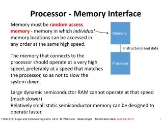
Implementation of Instructions • Fetch instruction • Send the PC to the memory location containing the next instruction • Read registers • fetch registers using fields of the instruction • lw needs just one register • most other instructions need two registers • Next steps depend on instruction class
Implementation of Instructions II • Once register operands have been fetched, they can be operated on • to compute a memory address (lw and sw) • to compute an arithmetic result (int ops) • to compare (for a branch) • Use output of the ALU
Implementations of Instructions III • Output of ALU is • written to a register in the case of arithmetic-logical instructions • used as an address in the case of load and store instructions • to determine the next instruction address in the case of branch instructions
More Implementation Details • Abstract, simplified view • Two types of functional units: • elements that operate on data values (combinational) • elements that contain state (sequential)
Combinatorial and Sequential Elements • The ALU is a combinatorial element • Other elements of the design are not combinatorial, but contain a state • An element with some internal storage is called a state element • State elements have at least two inputs: • data • clock (determines when data is written)
falling edge cycle time rising edge Clocking Methodology • We need to decide when signals can be read and written • We need to specify timing behavior • For simplicity, we assume an edge-triggered clocking strategy (synchronous design) • All storage elements are updated on either raising edge or falling edge:
Synchronous Design • Typical execution: • read contents of some state elements, • send values through some combinational logic • write results to one or more state elements
Refresh you memory! • Read Appendix B about Logic Design • Keywords • latch • D-flip flop • gates • clock • …
D-latch • Two inputs: • the data value to be stored (D) • the clock signal (C) indicating when to read & store D • Two outputs: • the value of the internal state (Q) and it's complement
D flip-flop Output changes only on falling clock edge
Conclusions • We will use D-flip flops to build the register file • We gradually build up the datapath • Simple components will allow us to do this • We add the control logic a little later • You will need a firm understanding of logic design • Study Chapter 4, read Appendix B