Download
1 / 35
350 likes | 374 Views
Learn about the latest advancements in the ALICE Central Trigger Processor revealed at the 12th LECC Workshop in Valencia 2006. The presentation covers the system overview, software framework, trigger classes, logic, data transmission, and past-future protection mechanisms.

E N D
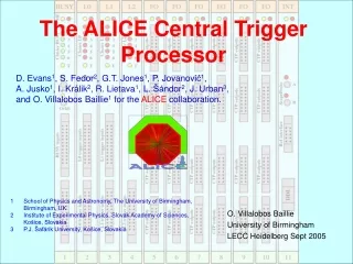
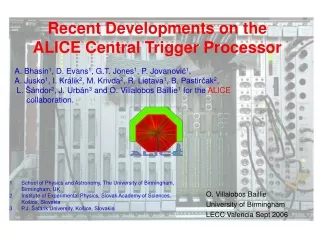
Recent Developments on the ALICE Central Trigger Processor A. Bhasin1, D. Evans1, G.T. Jones1, P. Jovanović1, A. Jusko1, I. Králik2, M. Krivda2, R. Lietava1, B. Pastirčak2, L. Šándor2, J. Urbán3 and O. Villalobos Baillie1 for the ALICE collaboration. O. Villalobos Baillie University of Birmingham LECC Valencia Sept 2006 • School of Physics and Astronomy, The University of Birmingham, Birmingham, UK • Institute of Experimental Physics, Slovak Academy of Sciences, Košice, Slovakia • P.J. Šafárik University, Košice, Slovakia
Plan of Talk • CTP Overview • ALICE conditions • Synopsis of requirements • Trigger data • CTP Design • Description of system and common features of boards. • Status • Software • Framework • Examples • Trigger-DAQ-ECS integration tests. • Summary O. Villalobos Baillie - 12th LECC Workshop - Valencia 2006
ALICE Running Conditions • The ALICE experiment aims to run in several different modes, both ion-ion and pp, giving very different requirements for multiplicity and rate. • Within a given mode, triggers with very different rates will be running concurrently. For example, in pp • We need high statistics minimum bias data (200 kHz) • We shall also run very low rate triggers, for exampe a high pT μμ trigger with an expected rate of a few Hz O. Villalobos Baillie - 12th LECC Workshop - Valencia 2006
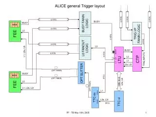
CENTRAL TRACKER ● pixel ● Silicon Drifts ● Silicon Microstrips ● TPC ● TRD ● TOF HIGH multiplicity tracking, Overall rate relatively low (TPC) HIGH data output SPECIAL DETECTORS ● ACORDE ● PHOS ● EMCAL ● HMPID DIMUON TRACKER ● absorber ● Tracking chambers ● Trigger chambers HIGH rate LOW(er) data output FORWARD DETECTORS ● T0 ● V0 ● FMD ● PMD O. Villalobos Baillie - 12th LECC Workshop - Valencia 2006
CTP Specification • 3 Trigger levels: • L0 inputs up to 800 ns; delivered to detector 1.2 μs from interaction; • L1 inputs to 6.1 μs; delivered to detector 6.5 μs from interaction; • L2 delivered to detector 88 μs from interaction. • 60 inputs • L024; L124; L212. • Up to 24 detectors • 6 partitions (clusters). • 4 past/future protection circuits. • 4 bunch crossing masks; 2 random triggers; downscaling. • Rare-event handling; interaction recording. O. Villalobos Baillie - 12th LECC Workshop - Valencia 2006
Trigger Classes and Logic • A trigger class consists of • A set of trigger inputs • A defined trigger output cluster • Specification of past-future protection, rare-event handling, downscaling, RoI handling. • TRIGGER LOGIC • It was found that almost all ALICE triggers require only AND logic • 44 classes allow only AND • classes also allow complement of input to be required • In addition, for 4 chosen inputs, a look-up table allows arbitrary logic • functions to be specified (e.g. to define INTERACTION). The result • of this logic can be used as an additional trigger input. O. Villalobos Baillie - 12th LECC Workshop - Valencia 2006
CTP Data • Trigger data are sent as TTC broadcasts with both L1 and L2 triggers • L1 message: calibration flag; readout control bits(4); segmented readout flag; L1 software class flag; L1 active trigger classes (50). • L2 message: bunch crossing ID(12); orbit ID(24); calibration flag; L2 software class; L2 cluster mask (6); L2 active trigger classes (50). • The same data is kept by the DAQ on the trigger LDC. • In addition, the trigger sends to the DAQ an interaction record, indicating for each orbit which bunch crossings gave an interaction (whether triggered or not) and its multiplicity classification (peripheral or semi-central). This is used for • Past-future protection checks • Evaluation of secondary vertices in reconstruction. O. Villalobos Baillie - 12th LECC Workshop - Valencia 2006
events e1 triggers e2 triggers e1 e2 L0 L1 L2 L0 L1 Past-Future protection I TPC drift time past/future protection interval • Programmable width 200 s • Programmable number of permitted interactions (up to 32) in 1 interval • 2 interaction inputs – low/high multiplicity events are recognised • Pb-Pb: pile-up is avoidable, several ‘piled-up’ peripheral events allowed, but only 1 central event. • p-p: pile-up is unavoidable, large number of events are tolerated in TPC, but only few events in ITS O. Villalobos Baillie - 12th LECC Workshop - Valencia 2006
Past-Future Protection II • In this example, we set past-future protection with a span of 3 BC and a threshold of 1 (plus the interaction being considered. • First interaction is OK • Second appears OK, but when second appears it is vetoed immediately, setting a past-future protection signal lasting 3 BC to prevent further interactions from being triggered. • First interaction would also be vetoed, in this case with a “second look” Δt after the interaction, looking at the previous 2Δt, where it would be again found that the past-future protection threshold had been exceeded. O. Villalobos Baillie - 12th LECC Workshop - Valencia 2006
Typical CTP board Layout • L0 board • ALTERA EPM3512 FPGA for VME control, close to J1 connector • ALTERA CYCLONE EPIC20 FPGA for main logic • On-board flash memory (Am29LV081) loaded through VME • 1 Mword 32 bit word ‘snapshot’ memory (2 CY7C1382 ICs) • PCF8591 ADC for readout of voltages and fuse status via I2C. O. Villalobos Baillie - 12th LECC Workshop - Valencia 2006
L0 Board O. Villalobos Baillie - 12th LECC Workshop - Valencia 2006
LTU board • Again basic layout similar • Capacity of FPGA can change – all are in CYCLONE series but both EPIC20F400C7 and EPIC12F324C7 have been used. • Front panels vary. O. Villalobos Baillie - 12th LECC Workshop - Valencia 2006
32 SCL 31 SDT 2 2 I C control bus 1 I C control bus 2 30 29 28 27 CTP BUSY 26 Interaction 1 25 Interaction 2 24 Strobe L2 Data 23 Strobe Data 1 Class L0 22 Data 2 Data Strobe 21 Cluster Class L1 BUSY 20 Data 19 18 17 Cluster L1 16 15 14 13 12 11 10 9 Cluster L0 8 7 6 5 Pre - pulse 4 ScopeProbe A 3 ScopeProbe B 2 Orbit 1 BC BUSY L0 L1 L2 FO1 FO2 FO3 FO4 FO5 INT FO6 1 2 3 4 5 6 7 8 9 10 11 Signal source Common ground connection Cluster signal groups Signal destinati on Serialised link, data and strobe line, 40 MHz 2 Bus termination I C control bus, clock and serial data CTP backplane O. Villalobos Baillie - 12th LECC Workshop - Valencia 2006
32 32 32 32 32 32 32 32 32 32 32 1 1 I2C2 I2C1 20 20 20 20 20 20 20 20 20 20 20 GND GND 10 10 10 10 10 10 10 10 10 10 10 (50µm thick) SMD resistor (100Ω, size 0603) Ground plane Kapton foil (100Ω diff. pairs) Rigidiser LVDS pair - LVDS pair + Not connected 10-pin IDC connector Tracks Ground BUSY L0 L1 L2 FO FO FO FO FO FO INT I2C signal 1 1 1 1 1 1 1 1 1 1 C A C A C A C A C A C A C A C A C A C A C A 75 μm double sided copper-clad Kapton film: signals transmitted as LVDS pairs. (CERN, SCEM 09.55.05.609.6) (CERN, SCEM 09.61.33.610.3) DIN41612 connector, a+c O. Villalobos Baillie - 12th LECC Workshop - Valencia 2006
Backplane • Plugs into J2 part of the 6U VME crate. O. Villalobos Baillie - 12th LECC Workshop - Valencia 2006
Birmingham Test Setup • Units used: • BUSY • L0 • L1 • L2 • 4´F0 • 2´LTU • TTCvi • TTCex • TTCvx O. Villalobos Baillie - 12th LECC Workshop - Valencia 2006
Minimum Propagation Time 20ns/division • Represents interval between arrival of signal at input of L0 board and output of trigger decision on FO board, with minimum internal delays. • Propagation through LTU in “global” mode is very fast (no processing) so full delay to output of LTU adds less than 10 ns to this result • Actual propagation delay when in use in ALICE will depend on what internal delays are set. O. Villalobos Baillie - 12th LECC Workshop - Valencia 2006
Current Status • Boards were designed at Birmingham and built through RAL. All now built and tested. • There are two full CTP setups being used in Birmingham, and two at CERN. Fifth will be installed in ALICE pit shortly. • One of CERN CTP setups connected to test boards in ALICE DAQ lab for full system tests. O. Villalobos Baillie - 12th LECC Workshop - Valencia 2006
Software • Software development is essential to operate the trigger. • The software framework for the trigger was agreed in 2003 • Main programming language: C • Interface to ECS: SMI++ and DIM (also DAQ) • Principal interface to DAQ uses ALICE DDL • Graphical interface: Python/Tk and Tcl/Tk • Monitoring: use ALICE AFFAIR (or MOOD) packages where possible (implies use of ROOT). O. Villalobos Baillie - 12th LECC Workshop - Valencia 2006
CTP Software Main Menu • Setting up of trigger parameters using additional panels • Classes • Clusters • p/f • Choice of counters for monitoring (all available) • Choice of signals to monitor on scope (50Ω termination) • Snapshot control, including browser to allow rapid visualization of snapshot results. O. Villalobos Baillie - 12th LECC Workshop - Valencia 2006
Example 1: Class Configuration • Example shows: • List of active classes, together with their trigger conditions, including which vetoes (p/f, rare trigger handling) and scaling options are demanded • Colours used to indicate settings and output clusters. Makes very compact display. O. Villalobos Baillie - 12th LECC Workshop - Valencia 2006
Example 2: Counters • Menu offers choice of counters to display. (All counters are registered.) • These are shown on separate panel, with choices for updating and output format. O. Villalobos Baillie - 12th LECC Workshop - Valencia 2006
Example 3: p/f again in snapshot browser • Two trigger inputs are active. rndtrg1 contributes to interaction definition (monitored by p/f) but not trigger. • Trigger scaledbc2defines trigger. • Top trigger output (l0clst1) uses p/f and is inhibited because of rndtrg1 activity • Bottom trigger output (l0clst4) does not use p/f and survives • Bottom trace (pf1) shows extent of p/f veto signal. O. Villalobos Baillie - 12th LECC Workshop - Valencia 2006
Snapshot Browser • Snapshot browser allows snapshots on different boards to be displayed together, with facilities for alignment of signals from the different boards (since snapshots will in general start at different times.) O. Villalobos Baillie - 12th LECC Workshop - Valencia 2006
CTP-DAQ-ECS Tests • Three areas • L1 and L2 trigger words are essential to DAQ equipment headers. Tests show these can be transferred to detector simulator (ALICE DDG module) allowing event building. • ECS uses detector partitions, which allow detector to be separated into non-overlapping parts with independent DCS, DAQ and trigger. CTP hardware does not reflect this, so software written (and tested) which imposes partition boundaries on allowed clusters. • Trigger generates special start-of-run and end-of-run events as required by ECS, which can be picked up in DDG. Idea is to use these to indicate start of data-taking, once detectors and DAQ have been configured at start of run. O. Villalobos Baillie - 12th LECC Workshop - Valencia 2006
Summary • CTP now built and tested, according to specification • CTP setups in operation at both Birmingham and CERN to allow continuing study of system and to provide training sessions. Fifth CTP setup ready to be installed in ALICE pit as soon as necessary. • Minimum propagation delay in CTP found to be 76.6ns, leading to estimate of <90ns for full system including LTUs. • Complete set of CTP software for testing and configuration exists. Further work on software for integration with other ALICE central systems and for more high level control and monitoring continues. • Commissioning in ALICE pit about to begin. O. Villalobos Baillie - 12th LECC Workshop - Valencia 2006
Past-Future in more detail • First check looks at the past at time when interaction happens. It can veto events in the future and save resources. It cannot remove events which were OK when their check occurred. • Second check is at end of p/f interval, and looks back for interval 2Δt. It can reject first event if a subsequent event renders it invalid. O. Villalobos Baillie - 12th LECC Workshop - Valencia 2006
Past-Future Protection II • Each logic block set with moving time window of length ΔTA/B, with thresholds on the number of interactions inside time window. • In ion-ion mode, block A checks for (semi)-central events (NO pile-up), block B for peripheral events (some pile-up tolerated) • In pp mode, both blocks use MB interaction; different thresholds set for TPC (wide pile-up tolerance) and ITS (restricted pile-up tolerance). O. Villalobos Baillie - 12th LECC Workshop - Valencia 2006
events e1 triggers e2 triggers e3 triggers L2 L1 e1 e3 L0 e2 L0 L1 L0 L2 L1 s 1.2 6.5 88 Trigger protocol e2 signals not generated by CTP, information is kept only in Interaction record L1 rejection: L1 is not generated(no explicit reject message) L2 rejection: There is always L2 message (L2accept or L2reject) Earliest time for next L0 is at the time of L1 (on the LTU output), i.e. no L0 between L0, L1 for 1 detector O. Villalobos Baillie - 12th LECC Workshop - Valencia 2006
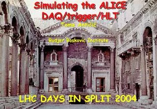
‘Rare’ events: simulation • In order to study event flow in ALICE, a generic model was developed (L. Musa; T. Anticić et al.) allowing study of events, controlled by trigger/DAQ protocols, from FE to main DAQ. • Study showed that without care, trigger rates for frequently ocurring triggers would dominate DAQ, meaning bandwidth was always saturated when a rare trigger arrived. O. Villalobos Baillie - 12th LECC Workshop - Valencia 2006
‘Rare’ events - solution • Solution is to use software signals from DAQ to flag when buffers are close to full, and at this point only allow trigger classes flagged as rare. (Sometimes not so rare.) • When buffers have emptied sufficiently, non-rare classes are again enabled. • Scalers have to be chosen so as to allow correct book-keeping for this on-off of non-rare triggers. Checked to be OK. O. Villalobos Baillie - 12th LECC Workshop - Valencia 2006
Design of Boards • The CTP electronics has been designed to fit onto 6 different kinds of 6U VME boards. • Trigger inputs are LVDS • A special J2 backplane transfers signals from one board to the next. • Outputs are sent to Local Trigger Units (LTUs) where conversion to output format occurs. O. Villalobos Baillie - 12th LECC Workshop - Valencia 2006
Local Trigger Unit (LTU) • Described in detail last year. • Serves as interface between CTP and detectors. • Produces detector specific signals (LVDS and TTC controls) which are then sent to detectors • Can also emulate all CTP functions so as to produce a full ALICE-like environment. • Accepts external input for use with test beam. • 53 LTUs built, some for ALICE experiment, some for detector groups for development work. O. Villalobos Baillie - 12th LECC Workshop - Valencia 2006
CTP emulation • Together with selector, LTU can run in STANDALONE mode, presenting the same FE interface as in GLOBAL mode • 7 legal sequences • Programs of max. 32 sequences are prepared in emulator memory. L1 and L2 data are fully programmable • Sequence execution triggered by Start signal derived from BC scaled down, random generator, external pulser or software request • Error prone flag enables programmable random errors in STANDALONE mode with chosen sequences in order to allow the FE electronics testing for error recovery • Errors on demand can be generated in both modes O. Villalobos Baillie - 12th LECC Workshop - Valencia 2006