Download
1 / 18
180 likes | 202 Views
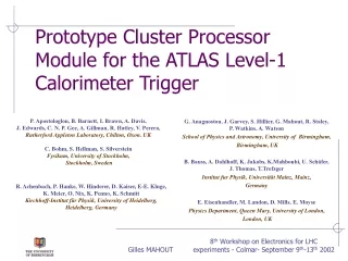
Prototype Cluster Processor Module for the ATLAS Level-1 Calorimeter Trigger. P. Apostologlou, B. Barnett, I. Brawn, A. Davis, J. Edwards, C. N. P. Gee, A. Gillman, R. Hatley, V. Perera, Rutherford Appleton Laboratory, Chilton, Oxon. UK C. Bohm, S. Hellman, S. Silverstein

E N D
Prototype Cluster Processor Module for the ATLAS Level-1 Calorimeter Trigger P. Apostologlou, B. Barnett, I. Brawn, A. Davis, J. Edwards, C. N. P. Gee, A. Gillman,R. Hatley, V. Perera, Rutherford Appleton Laboratory, Chilton, Oxon. UK C. Bohm, S. Hellman, S. Silverstein Fysikum, University of Stockholm, Stockholm, Sweden G. Anagnostou, J. Garvey, S. Hillier, G. Mahout,R. Staley, P. Watkins, A. Watson School of Physics and Astronomy, University of Birmingham, Birmingham, UK B. Bauss, A. Dahlhoff, K. Jakobs, K.Mahboubi, U. Schäfer, J. Thomas, T.Trefzger Institut fur Physik, Universität Mainz, Mainz, Germany E. Eisenhandler, M. Landon, D. Mills, E. Moyse Physics Department, Queen Mary, University of London, London, UK R. Achenbach, P. Hanke, W. Hinderer, D. Kaiser, E-E. Kluge, K. Meier, O. Nix, K. Penno, K. Schmitt Kirchhoff-Institut für Physik, University of Heidelberg, Heidelberg, Germany Gilles MAHOUT
ATLAS Level-1 Calorimeter Trigger System • Level -1 Trigger Requirements • Reduce 1 GHz interaction rate to a 75 kHz trigger rate • Provide trigger multiplicity information to the CTP: • e/g and t/hadron • jets • missing and total Et • muons (separate trigger) • Provide Region of Interest (RoI) information to the Level-2 trigger system • Provide data for monitoring and diagnostics Gilles MAHOUT
S S ATLAS Level-1 Calorimeter Trigger System ROD RoI Cluster Processor e/g and t/h Cluster finding DAQ DAQ Glinks Pre-Processor 10-bit FADC FIFO, BCID LUT BC Mux Counting Calorimeters LAr/TileCal Level-1 CTP LVDS Counting Level-2 SET, ET ROD RoI Jet finding ET sum / Ex Ey Jet/Energy Processor DAQ DAQ Real Time Asynchronous Gilles MAHOUT
CPM CPM CPM CMM CMM Cluster Processor Module (CPM): Requirements • Identify possible isolated electrons, photons and semi-hadronic t decays • Calculate multiplicities of e/g candidates and t candidates for different threshold conditions on Et • Transmit these multiplicities as input to the Level-1 trigger decision (multiplicities are summed from individuals CPMs by the Common Merger Modules) • Transmit Trigger Tower (TT) data, multiplicities and RoI co-ordinates to ReadOut Driver (ROD) Modules Cluster Processor Crate ×4 TCM x14 Gilles MAHOUT
Cluster Finding Algorithm • A 4x4 window is defined for EM and Had: 32 TT (0.1x01) in total • This window slides by 0.1 in eta and phi to fully cover the calorimeter • Within this window, we define • 4 1x2 trigger clusters in central 2x2 region • Isolation ring sums in had and em • for e/g, 1 central 2x2 sum hadronic veto region • 1 central RoI cluster, sum of the central 2x2 towers for both calorimeters • The Window is declared a candidate trigger object if : • The RoI cluster is a local maximum • At least one of the trigger clusters is above a trigger threshold • All isolation and veto sums are below their thresholds Gilles MAHOUT
Cluster Finding Algorithm: Cluster Processor Chip • Thanks to large and fast electronic devices such as FPGAs, a chip has been designed to process 8 4x4 windows • The limited available I/O requires serialisation of data @ 160 MHz • 8 CP chips can populate one CPM • But the sustainable input bandwidth for data of the board requires: • To reduce the data flow before reaching its input • To share Trigger Tower data between CP chips onboard, and across a custom-built backplane Gilles MAHOUT
Data Flow: across the Cluster Processor 6400 Triggers Towers (TT 0.1x0.1) x 8 bits (256 GeV) 14 Modules BC-Mux Serialised 4 Crates LVDS @ 400 Mbit/s f h TT x14 CPM CPM CPM CPM Clk CPM CPM CPM CPM CPM CPM CPM CPM CPM CPM CPM CPM Out Reduced by 8 280 TT/board 51200 bits/25 ns reduced by 2 Gilles MAHOUT
Cpm i+1 Cpm i-1 Cpm i Data Flow: across the CPM • Each board processes 64 4x4 windows through 8 chips • One chip processes 8 4x4 windows with TT: • directly from the input of the board • from adjacent modules in the same crate, fan out through the backplane • from its adjacent neighbours • In real time, the CPM has to • Receive 80 LVDS signals • Fan in/out 120 TTs from/to its adjacent modules • Transmit multiplicity information to CMM • A custom backplane has been built: about 1150 pins per slot are needed to handle all signals from CPM fan out, and CPMs and CMMs. Gilles MAHOUT
LVDS CP SRL Cluster Processor Module implementation (1) • Collect data from PreProcessor Module via 80 400 Mbit/s LVDS links • Collect fan-out data @ 160 MHz from neighbouring modules • 80 LVDS deserialisers convert data to 40 MHz 10-bit parallel word • 20 Serialiser (SRL) Chips distribute data @ 160 MHz : • Onboard to perform cluster finding algorithm • To adjacent processor modules Gilles MAHOUT
ROC LVDS HIT CP SRL Cluster Processor Module Implementation (2) • 8 CP chips perform the Cluster Finding Algorithm • 2 Hit Merger chips calculate and transmit multiplicities to Level-1 Trigger decision via Common Merger Module • 2 ROC chips pipeline Trigger Tower data, multiplicities, and RoIs co-ordinate within 3.2 ms • On Level-1 request, send previous information to ROD Module to help build Level-2 decision Gilles MAHOUT
Cluster Processor Module: Serialiser Chip • The serialiser chip performs 2 tasks: • Multiplexes and re-serialises data at 160 MHz to perform the cluster finding algorithm : Real Time Data Path • Pipelined data ,waiting for a readout request: Asynchronous Path The design has been implemented in a FPGA Xilinx VirtexE XCV100E 20x SRL SRL Backplane ROC x 2 CP CP x 8… CP Gilles MAHOUT
Cluster Processor Chip • Design successfully implemented in FPGA Xilinx VirtexE 1000E: 1.5 million gates – 660 inputs • One chip provides as output: • Which sets of thresholds among 16 have been passed • Where a RoI has been identified • Simulation shows the total functionality of the CP chip is performed in 6 clock cycles: • An extra .5 clock cycle is needed to merge and calculate the multiplicity for each threshold of all the chips. This is done by the HIT merger (XCV100E). Synchronisation Deserialisation BC Demux Algor. Thresh. Comp. Clocking Out Gilles MAHOUT
Cluster Processor Module: DaQ Readout Controller • Data from CP chips and Serialisers are pipelined and sent to ROD on Level-1 request via serial links (Glinks) CP CP CP X8 x20 En_Readout Data Readout Controller L1A HIT SRL En_Readout Bunch Crossing Number SRL 1 3 5 G-links SRL Gilles MAHOUT
Cluster Processor Module: Implementation • Full specification board exists ! • 9U Board: 16 layers • 80 LVDS deserialiser DS92LV1224 • 20 FPGA Xilinx Virtex XCV100E: Serialiser chip • 8 FPGA Xilinx Virtex XCV1000E: CP chip • 2 Virtex XCV100E merge multiplicities of all CP chips • 2 Virtex XCV100E act as the readout controller of the RoIs and Data path • FPGA configurations are stored in FlashRam Gilles MAHOUT
Cluster Processor Module: Local Test Setup • Custom built 9U backplane with fan in/out of data and a reduced VME bus • Timing and Control Module • 6U Concurrent CPU mounted in 9U adaptor • Linux system CPU CPM TCM Gilles MAHOUT
Cluster Processor Module: Stand-Alone Tests • FlashRam successfully downloaded via VME • Dual-port Ram of the Serialiser has two functions: • pipeline for the readout • playback memory to send data to the CP chip (no need of external LVDS signals) • Calibration pattern correctly delivered to CP chips, needed to synchronise all their inputs 10 ns/div Gilles MAHOUT
Cluster Processor Module: Real Time Data Test • Dual-port Ram loaded with Random pattern • CP chip loaded with a debugging configuration (instead of Cluster Finding algorithm) to check all inputs are synchronised correctly • Data recovered successfully inside CP chip Gilles MAHOUT
Cluster Processor Module: Conclusion • I/O constraints overcome successfully with high bandwidth • Large FPGA technology has been used successfully • Simulated latency of 6.5 ticks • Need more integration tests and external LVDS signals • Slice test planned for next year with other Level-1 trigger modules currently under similar stand-alone tests Gilles MAHOUT