Download
1 / 70
1.12k likes | 2.2k Views
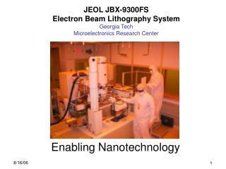
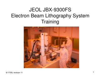
JEOL JBX-9300FS Electron Beam Lithography System Training. Course Outline. Explain hardware column, lenses, amplifiers field, chip, subfield shot pitch, beam diameter D = (I * t)/A Calibration AE & BE marks INITAE, INITBE, PDEFBE, SUBDEFBE, DISTBE HEIMAP Substrate various cassettes

E N D
Course Outline • Explain hardware • column, lenses, amplifiers • field, chip, subfield • shot pitch, beam diameter • D = (I * t)/A • Calibration • AE & BE marks • INITAE, INITBE, PDEFBE, SUBDEFBE, DISTBE • HEIMAP • Substrate • various cassettes • global & chip mark alignment • virtual chip mark height detection • Pattern Preparation • CAD file preparation • linkCAD conversion • file transfer • JBXFiler • Job Deck & Schedule File • Schd and Array check • ALD & Exposure • Resist Exposure & development • positive & negative resists • contrast • liftoff, etching • Proximity Effect • Website
Why E-beam Lithography? • exceeds patterning capability of optical lithography • easily pattern sub-micron features • MiRC has demonstrated 6.5nm features • patterns rapidly created from CAD file • no mask necessary like optical lithography • rapid turn around on design modifications, ideal for research
4nm diameter Gaussian spot electron beam 50kV/100kV accelerating voltage 50pA – 100nA current range 50MHz scan speed +/- 100um vertical range automatic focus +/- 2mm vertical range manual focus ZrO/W thermal field emission source vector scan for beam deflection max 300mm (12") wafers with 9" of writing area < 20nm line width writing at 100kV < 20nm field stitching accuracy at 100kV < 25nm overlay accuracy at 100kV JBX-9300FS key features
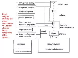
Gun Gun Control Blanking Control Pattern Proc. and control Electron Opics Deflection Control Electron Optics Control Computer stage motor stage x-interferometer Stage Control stage motor y-interferometer Generic Block Diagram reference marks
ZrO/W emitter Suppressor Electron gun First anode Second anode Acceleration electrodes Ground anode First alignment coil Second alignment coil Blanking aperture Blanking electrode Second lens Zoom lenses Dynamic focus correction electrode Third lens Third alignment coil Objective aperture Dynamic astigmatism correction electrode Subsidiary deflector (SUBDEF) Electromagnetism astigmatism correction electrode Objective lens Main deflector (PDEF) Backscattered electron detector Workpiece surface Column
Beam & Stage Position Stage position accuracy = λ / 1024 = 0.62nm
Stage w/o Cassette laser mirrors cassette goes here
Field Stitching 500 µm (100kV) 500 µm (100kV)
Within Field Writing Vector scan
4” Wafer with Chips 2mm 2mm
Example “Chip” Subfields 4um 4um 500um Field 500um beam diameter Chip shot pitch
Objective Aperture larger aperture = larger beam diameter, more current smaller aperture = higher resolution aperture beam diameter min resolution current range 3,4,5 4 – 9nm < 20nm 50pA – 2nA 6 8 – 14nm 30nm 2nA – 7nA 7 30nm 60nm 10nA Most of the time, the 9300 will be set to aperture #3 and 2nA beam current.
Dose Equation where D = dose (µC/cm2) I = current (A) t = time (sec) A = exposure area (cm2)
Job Time Estimate if D = 200 µC/cm2 A = 1 cm2 I = 2nA then t = 27 hours 46 min time calculator at http://nanolithography.gatech.edu/tcalc.php
Shot Pitch • Shot pitch is equivalent to pixel value – the smaller the shot pitch, the better the feature definition • Shot pitch is limited by scanning frequency of the SUBDEF (max = 50MHz)
Effect of Shot Pitch Energy deposited in resist Consider a line is exposed with 200uC/cm^2 dose. Depending on the number of pixels that the line-width is divided into, the line edge roughness (LER) and line-width will vary. x The graph at right shows the cross-section of energy deposition profile of a line with 1,2,4 and n pixels.
Minimum Shot Pitch Calculation • t = D.A/I • A = area of pixel = a2 • t = 1/fclk where fclk is the maximum scanning frequency of the amplifier • a = √I/(fclk.D)
Explain hardware • column, lenses, amplifiers • field, chip, subfield • shot pitch, beam diameter • D = (I * t)/A • Calibration • AE & BE marks • INITAE, INITBE, PDEFBE, SUBDEFBE, DISTBE • HEIMAP • Substrate • various cassettes • global & chip mark alignment • virtual chip mark height detection • Pattern Preparation • CAD file preparation • linkCAD conversion • file transfer • JBXFiler • Job Deck & Schedule File • Schd and Array check • ALD & Exposure • Resist Exposure & development • positive & negative resists • contrast • liftoff, etching • Proximity Effect • Website
Stage faraday cup AE, BE mark SEM sample
INITAE metal grid y - scan y-scan x - scan x-scan ds/dy ds/dx pn junction mark center position
INITBE Au cross on Si substrate y - scan x - scan x-scan ds/dy ds/dx y-scan mark center position
PDEFBE & SUBDEFBE gain 4 um 500 um 3 1 2 top 482um 4 um 4 6 482um 500 um 5 rotation right left 8 9 7 bottom PDEFBE 4 points measured x & y gain correction x & y rotation correction SUBDEFBE 9 points measured x & y gain correction x & y rotation correction shift
HEIMAP • measures height across wafer on defined array positions (adjustable by user) • takes average height and uses that for focus value for writing everywhere • appropriate for 100pA & 1nA current • not appropriate for 10nA – use virtual chip mark height detection
Explain hardware • column, lenses, amplifiers • field, chip, subfield • shot pitch, beam diameter • D = (I * t)/A • Calibration • AE & BE marks • INITAE, INITBE, PDEFBE, SUBDEFBE, DISTBE • HEIMAP • Substrate • various cassettes • global & chip mark alignment • virtual chip mark height detection • Pattern Preparation • CAD file preparation • linkCAD conversion • file transfer • JBXFiler • Job Deck & Schedule File • Schd and Array check • ALD & Exposure • Resist Exposure & development • positive & negative resists • contrast • liftoff, etching • Proximity Effect • Website
Available Cassettes • Wafer • 75mm, 100mm, 150mm, 200mm diameter • 300mm can be purchased for up to 9” square writing area • Masks • 5” mask, 6” mask • Pieces • minimum 3 x 5mm piece
Explain hardware • column, lenses, amplifiers • field, chip, subfield • shot pitch, beam diameter • D = (I * t)/A • Calibration • AE & BE marks • INITAE, INITBE, PDEFBE, SUBDEFBE, DISTBE • HEIMAP • Substrate • various cassettes • global & chip mark alignment • virtual chip mark height detection • Pattern Preparation • CAD file preparation • linkCAD conversion • file transfer • JBXFiler • Job Deck & Schedule File • Schd and Array check • Resist Exposure & development • positive & negative resists • contrast • liftoff, etching • Proximity Effect • Website
CAD file conversion linkCAD AutoCAD .DXF file or GDSII file CADENCE file or JEOL01 file JBXFILER JEOL52 v3.0 file
SCHD execution specifies 1. wafer cassette window 2. calibration file 3. base dose 4. job deck file(s) to use 5. shot pitch specifies 1. JEOL52 v3.0 pattern file 2. how to arrange on wafer 3. shot modulation 4. type of calibration 5. beam current
Explain hardware • column, lenses, amplifiers • field, chip, subfield • shot pitch, beam diameter • D = (I * t)/A • Calibration • AE & BE marks • INITAE, INITBE, PDEFBE, SUBDEFBE, DISTBE • HEIMAP • Substrate • various cassettes • global & chip mark alignment • virtual chip mark height detection • Pattern Preparation • CAD file preparation • linkCAD conversion • file transfer • JBXFiler • Job Deck & Schedule File • Schd and Array check • Resist Exposure & development • positive & negative resists • contrast • liftoff, etching • Proximity Effect • Website
Negative/Positive Resist exposing e-beam exposing e-beam substrate NEGATIVE POSITIVE select appropriate resist for process and to minimize writing time
resist vs. dose curves more sensitive negative positive resist thickness less sensitive resist thickness dose dose more contrast resist thickness less contrast dose
Resists on hand at MiRC • Negative resist • XR-1541 (HSQ) • good etch resistance (HSQ is basically SiO2) • excellent resolution (6.5nm) • slow • expensive ($4/mL) • ma-N 2403 (Novolak) • good etch resistance • optical DUV exposable • faster than HSQ • moderately priced ($2/mL) • poor adhesion to quartz • Positive resists • ZEP520A • good etch resistance • fast • good resolution (~ 10nm) • expensive ($3/mL) • PMMA • cheap ($1/mL) • good for liftoff • high resolution (< 10nm) • poor etch resistance • slow