Homework
This document provides a comprehensive overview of computer architecture. It discusses the roles of the processor, memory, and I/O devices, including how the processor controls the fetching and execution of instructions. Key concepts such as the signal meanings, address and data buses, and various assembly language instructions are covered. A detailed examination of the 80386 processor model highlights its registers, the arithmetic logic unit (ALU), and the communication mechanisms between components. This is essential for students and professionals working with computer systems.

Homework
E N D
Presentation Transcript
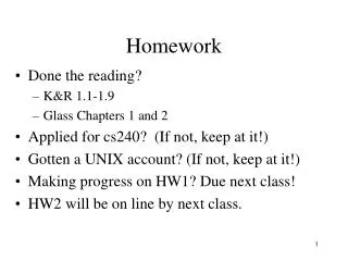
Homework • Reading • Professional Assembly Language, pp 17-32, 34-37 • Continue work on mp1 • Questions? • Lab with your assigned section this week
General Computer Architecture • Processor • Controls fetching and execution of instructions • Moves data between memory, registers, the arithmetic / logic unit (ALU), and I/O devices • Memory • Stores instructions and data • I/O Devices • Bring data into system • Send data out from system
General Computer Architecture C-Bus (M/IO#, W/R#, and D/C# Signals) Processor Fetch and Execute Control Address Bus I/O Devices Arithmetic Logic Unit Memory Registers Data Bus
Signals and Busses • A “signal” is a logical value represented as a voltage on a wire inside the machine • A signal is binary (two states – on and off) • There is a specific meaning assigned to each value of a signal, e.g. M/IO# • M/IO# = 1 means access memory • M/IO# = 0 means access an I/O device • A “bus” is a group of signals with one purpose
Processor Model • An assembly language programmer usually thinks of the processor in terms of its: • Registers • Arithmetic Logic Unit (ALU) • Instructions • Address and data bus sizes • I’ll be simplifying the textbook material for now • We’ll come back to that material later
80386Processor Model - Registers %ax %eax %ah %al Memory Address Memory %bx %ebx %bh %bl 0x00000000 %cx M/IO# %ecx %ch %cl W/R# %dx D/C# %edx %dh %dl A-Bus (32 bits) %esp %sp %ebp %bp D-Bus (32 bits) %esi %si %edi %di 0xFFFFFFFF
Processor Model - Registers • Additional status and control registers • Instruction Pointer/Extended Instruction Pointer • Extended Flags Register %eip %ip %eflags
Arithmetic Logic Unit • Capable of performing arithmetic • Addition, Subtraction, Multiplication, Division • Capable of performing logic operations • and, or, exclusive or • Takes operands from source(s) specified in the instruction • Delivers results to destination specified in the instruction
Processor Model - Instructions • Instructions to move a constant into a register • movb $54, %al Move 5410 to al register • movb $0x36, %al Move 3616 to al register • movb $'6', %al Move digit 6 to al register • Instructions to move data between registers • movl %ebx, %eax • movw %bx, %ax • movb %bh, %ah • movb %bl, %al
Processor Model - Instructions • Instructions to add or subtract a constant to a register addb $10, %bl subb $10, %bl • Instructions to add or subtract a register to another register addb %bh, %bl subb %bh, %bl
Busses • Address Bus • Driven by the processor (Simplified for now) • Processor presents address of memory location or I/O device being accessed on the busses • Each memory or I/O device determines if the value on the address bus and M/IO# signal selects it or not • When selected, memory or I/O device gets data from data bus or puts data on data bus based on W/R#
Busses • Data Bus • Used as a conduit for data between devices • Specific operations performed on the data bus are driven by control and address bus signals • Can be driven by processor, memory, or an I/O device depending on the type of transfer done • Interfaces to data bus require a special kind of “tri-state” logic which we will discuss later
Busses • Control Bus Signals • M/IO# signal selects • Memory when set (= 1) • I/O devices when reset (= 0) • W/R# signal moves data from • Processor to memory or I/O device when set (= 1) • Memory or I/O device to processor when reset (= 0) • D/C# signal indicates • Data (instruction execute phase) when set (=1) • Control (instruction fetch phase) when reset (=0)
Fetch Cycle • On each fetch cycle, processor • Puts signal M/IO# = 1 on control bus • Puts signal W/R# = 0 on control bus • Puts signal D/C# = 0 on control bus • Puts address of next instruction from the EIP register on address bus signals • Reads next instruction on data bus
Fetch Cycle C-Bus (M/IO# = 1, W/R# = 0, D/C# = 0) Processor Fetch and Execute Control Address From EIP Register I/O Devices Arithmetic Logic Unit Memory Registers Data Bus (Instruction)
Execute Cycle • On each execute cycle, processor • May or may not need to access memory or I/O • Some instructions act inside processor only, e.g. instruction to move a constant to a register • When processor accesses memory or an I/O device during execute cycle, there are four possible combinations:
Execute Cycle (Memory Read) C-Bus (M/IO# = 1, W/R# = 0, D/C# = 1) Processor Fetch and Execute Control Address I/O Devices Arithmetic Logic Unit Memory Registers Data Bus (Data From Memory)
Execute Cycle (Memory Write) C-Bus (M/IO# = 1, W/R# = 1, D/C# = 1) Processor Fetch and Execute Control Address I/O Devices Arithmetic Logic Unit Memory Registers Data Bus (Data To Memory)
Execute Cycle (I/O Read) C-Bus (M/IO# = 0, W/R# = 0, D/C# = 1) Processor Fetch and Execute Control Address I/O Devices Data In Arithmetic Logic Unit Memory Registers Data Bus (Input Data)
Execute Cycle (I/O Write) C-Bus (M/IO# = 0, W/R# = 1, D/C# = 1) Processor Fetch and Execute Control Address I/O Devices Data Out Arithmetic Logic Unit Memory Registers Data Bus (Output Data)