Download
1 / 10
100 likes | 252 Views
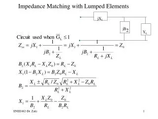
LHC impedance: Comparison between phase 1 and IR3MBC – follow-up. N. Mounet, B. Salvant and E. M é tral Acknowledgements: G. Rumolo, A. Rossi. !! Still preliminary results !!. Introduction.

E N D
LHC impedance: Comparison between phase 1 and IR3MBC – follow-up N. Mounet, B. Salvant and E. Métral Acknowledgements: G. Rumolo, A. Rossi. !! Still preliminary results !! N. Mounet, B. Salvant and E. Métral - BE/ABP/LIS - 24/11/2010
Introduction • IR3MBC is the collimation layout foreseen as an intermediate step before the phase 2 collimation → combined momentum – betatron cleaning in IR3. • Impedance model: • Collimators open in IR7, closer to the beam in IR3 and some additional collimators, including in cold sections (settings provided by A. Rossi), • Rest of the machine as for phase 1: • Beam screens, • Warm pipe, • MBW+MQW warm magnets, • Broadband impedance from design report. • Headtail simulations: • Non linear bucket, • Chromaticity = 2 in both planes, • Kick=0.1 sigma in both planes, • Nominal parameters for top energy (7TeV/c, Qx=64.31, Qy=59.32, norm. transverse emittances 3.75 mm.mrad (1 sig), long. emittance 2.5 eVs, RF voltage 16 MV, bunch length 7.55 cm, E/E (2 sig)=0.22e-3 ). N. Mounet, B. Salvant and E. Métral - BE/ABP/LIS - 24/11/2010
Multibunch modes: horizontal Better in horizontal, but… Stability diagrams from the octupoles N. Mounet, B. Salvant and E. Métral - BE/ABP/LIS - 24/11/2010
Multibunch modes: vertical … worse in vertical. In particular, huge tune shift (~1.3 10-3) with IR3MBC option. BUT this is supposed to be damped by transverse feedback. Now, is the real part of the tune shift an issue (for transverse mode coupling instability - TMCI - threshold) ? Stability diagrams from the octupoles N. Mounet, B. Salvant and E. Métral - BE/ABP/LIS - 24/11/2010
Horizontal and vertical dipolar (driving) impedance Confirm a much stronger vertical impedance with IR3MBC w.r.t. phase 1 (red vs.magenta) above ~105 Hz) N. Mounet, B. Salvant and E. Métral - BE/ABP/LIS - 24/11/2010
Largest impedance contributors in IR3MBC configuration • For those horizontal collimators: • - very small halfgap due to small s (from small bx), • quite large by, • Large vertical impedance (but not horizontal since bx is 10 times smaller). N. Mounet, B. Salvant and E. Métral - BE/ABP/LIS - 24/11/2010
Vertical dipolar impedance: largest contributors Rest of the machine = everything that is not a collimator in the current impedance model Above a few MHz,one single IR3MBC collimator gives the same imag. part as the totality of the phase 1 collimators. N. Mounet, B. Salvant and E. Métral - BE/ABP/LIS - 24/11/2010
Single-bunch TMCI instability threshold (Headtail) In horizontal Without octupoles In vertical Vertical modes (coupling due to tilted collimator) Large positive tune shift of vertical mode -1 TMCI in the vertical plane at 1.4 1011 p+/bunch (vs 3.4 1011 in phase 1) N. Mounet, B. Salvant and E. Métral - BE/ABP/LIS - 24/11/2010
Single-bunch TMCI instability threshold In horizontal With octupoles at 500A In vertical The TMCI threshold seems higher (~ 1.9 1011 p+/b), but we need to simulate more turns to be sure. N. Mounet, B. Salvant and E. Métral - BE/ABP/LIS - 24/11/2010
Conclusions • At 7TeV, with the IR3MBC option, the horizontal impedance is lower than in phase 1, but the vertical one is much larger (for the imaginary part, factor between 1.5 at 10kHz and 3 at 10 GHz). • In consequence, the multibunch transverse instability (thought to be the most critical effect at 7TeV) is a more critical issue than in phase 1 (well beyond the stability diagram). But this should be damped by the transverse feedback system. • Without octupoles, the effect on single-bunch TMC (transverse mode coupling) instability threshold of such an impedance is worse by more than a factor two between IR3MBC and phase 1, according to Headtail simulations. With octupoles currents one needs to simulate more turns to be sure, but threshold is at least of 1.9 1011protons per bunch.. • The multibunch effect on the TMC instability threshold has still to be checked (involve parallel Headtail multibunch simulation, code is still under development). According to earlier results by Scott Berg it could be worse (http://www.slac.stanford.edu/cgi-wrap/getdoc/slac-pub-6829.pdf). N. Mounet, B. Salvant and E. Métral - BE/ABP/LIS - 24/11/2010

![G5 - ELECTRICAL PRINCIPLES [3 exam questions - 3 groups]](https://cdn0.slideserve.com/382273/g5-electrical-principles-3-exam-questions-3-groups-dt.jpg)