Download
1 / 25
250 likes | 627 Views
The Development of Psec-Resolution TDC for Large Area TOF Systems. Fukun Tang Enrico Fermi Institute University of Chicago. With Karen Byrum and Gary Drake (ANL) Shreyas Baht, Tim Credo, Henry Frisch, Harold Sanders and David Yu (UC). From H. Frisch.

E N D
The Development of Psec-Resolution TDC for Large Area TOF Systems Fukun Tang Enrico Fermi Institute University of Chicago With Karen Byrum and Gary Drake (ANL) Shreyas Baht, Tim Credo, Henry Frisch, Harold Sanders and David Yu (UC)
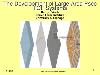
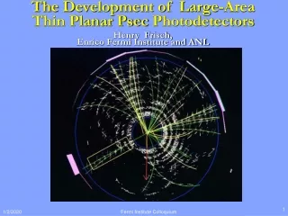
From H. Frisch Output at anode from simulation of 10 particles going through fused quartz window- T. Credo, R. Schroll Major advances for TOF measurements: Ability to simulate electronics and systems to predict design performance Jitter on leading edge 0.86 psec
Requirement: Psec-Resolution TDC MCP_PMT Output Signal Start 500pS Reference Clock Stop Tw 1 ps Resolution Time-to-Digital Converter!!!
Approaches & Possibilities (1) TAC-ADC 1/4 “Zero”-walk Disc. TAC Driver 11-bit ADC Receiver PMT 2 Ghz PLL REF_CLK 4x1Ghz PLL psFront-end (Timing Module Option #1)
TAC-ADC: Simulation Result Electronics with typical gate jitters << 1 psec
Approaches & Possibilities (2) Time Stretcher 1/4 “Zero”-walk Disc. Stretcher Driver 11-bit Counter Receiver PMT CK5Ghz 2 Ghz PLL REF_CLK psFront-end (Timing Module Option #2)
Time Stretcher:Simulation Result x200 StretchedTime Interval (Output Signal ) Stretched Time = 274ns (pedestal=74ns) 1ns Time Interval (Input Signal) 0 50ns 100ns 150ns 200ns 250ns 300ns
VCO: Submission of Oct. 2006 Ultimate Goal: • To build TDC with 1 pSec Resolution for Large Scale of Time-of-Flight Detector. Primary Goal: • To build 2-Ghz VCO, key module of PLL that generates the TDC reference signal • Cycle-to-Cycle Time-jitter < 1 ps • To evaluate IHP SG25H1/M4M5 Technology for our applications • To gain experiences on using Cadence tools (Virtuoso Analog Environment) • Circuit Design(VSE) • Simulation(Spectre) • Chip Layout(VLE, XLE, VCAR) • DRC and LVS Check (Diva, Assura, Calibre) • Parasitic Extraction(Diva) • Post Layout Simulation(Spectre) • GDSIIStream out • Validation • Tape Out
Diagram of Phase-Locked Loop CP Fref I1 Uc PD VCO F0 LF I2 1N PD: Phase Detector CP: Charge Pump LF: Loop Filter VCO: Voltage Controlled Oscillator
IHP (SG25H1) 0.25mm SiGe BiCMOS Technology • 0.25mm BiCMOS technology • 200Ghz NPN HBT (hetero-junction bipolar transistor) • MIM Capacitors (layer2-layer3) ( 1f/1u2 ) • Inductors (layer3-layer4) • High dielectric stack for RF passive component • 5 metal layers (Al) • Digital Library: Developing
2-GHz BiCMOS VCO Schematic Negative Resistance and Current-Limited Voltage Control Oscillator with Accumulating PMOS Varicap and 50W Line Drivers
V-F Plot (3 model cases @ 27C-55C) Frequency Temperature:27C-55C Supply:VDD=2.5V VControl varied 0.18V VControl
Phase Noise ( 3 model cases @ 27C) @100KHz offset Worst Typical Best Temperature:27C Supply:VDD=2.5V
2-GHz VCO Performance Summary (1) T=27C f0 = 2 GHz phase noise: dBc/Hz@100K offset
2-GHz VCO Performance Summary (2) T=55C f0 = 2 GHz phase noise: dBc/Hz@100K offset
Diagram of Post Layout Simulation Schematic Analog_extracted
Transit Analysis: Comparison of Schematic and Post Layout Simulations Outputs@50W loads Schematic Post Layout
V-F Plot: Comparison of Schematic and Post Layout Simulations Frequency PostLayout Schematic Vcontrol
Phase Noise: Post Layout SimulationsVDD=2.5V Temp.=27C, 55C Phase Noise @100KHZ offset
Conclusion (1) VCO time-jitter met our requirement. (2) Post layout simulation matched schematic simulation very well. (3) Some problems we have encountered with pcell library, layout, DRC, LVS and auto-routing functionalities. (4)Ready for October Submission.