Download
1 / 59
590 likes | 594 Views
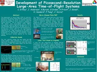
This article discusses the development of large-area picosecond time-of-flight (TOF) systems and their impact on momentum and energy measurements in various fields such as particle physics, medical imaging, accelerators, and more.

E N D
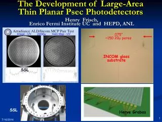
The Development of Large-Area Psec TOF Systems Henry J. Frisch Enrico Fermi Institute and Physics Dept University of Chicago IBM Psec Timing
Resolution on time measurements translates into resolution in space, which in turn impact momentum and energy measurements. • Silicon Strip Detectors and Pixels have reduced position resolutions to ~5-10 microns or better. • Time resolution hasn’t kept pace- not much changed since the 60’s in large-scale TOF system resolutions and technologies (thick scint. or crystals, PM’s, NIM/Camac/VME TDC’s) • Improving time measurements is fundamental , and can affect many fields: particle physics, medical imaging, accelerators, astro and nuclear physics, laser ranging, …. • Need to understand what are the limiting underlying physical processes- e.g. source line widths, photon statistics, e/photon path length variations. • What is the ultimate limit for different applications? Introduction IBM Psec Timing
OUTLINE • Introduction: why picosec, and why `large-area’? • HEP needs: particles and quark flow, heavy particles, displaced vertices, photon origin • Three key developments since the 60’s: MicroChannel Plates (MCPs), 200 GHZ electronics, and `end-to-end’ simulation • The need for `end-to-end’ simulation • Positron-Emission Tomography (PET): looks like HEP: data rate, # of channels, S/N, data-acquisition, real-time imaging (not my area..) • What determines the ultimate limits? Applications? IBM Psec Timing
From 2005 slide Now with David Yu , Jakob Van Santen (students), Karen Byrum (physicist) and Gary Drake (Elec. Engineer) of Argonne National Lab, and Prof.’s Chin-Tu Chen and Chien-Minh Kao of the Dept of Radiology, Univ. of Chicago. Also have a MOU in progress with Saclay in France, and a close working relationship to Jerry Va’vra at SLAC. Have developed a community (e.g. Saclay workshop) IBM Psec Timing
My motivation- High Energy Collisions- understnding the basic forces and particles of nature- hopefully reflecting underlying symmetries The CDF detector at Fermilab- 5000 tons… more than a million channels But small compared to Atlas and CMS! IBM Psec Timing
Fermilab (40 miles west of Chicago) Superconducting Tevatron Ring (980 GeV) P’s CDF is here Pbars 1 km radius Antiproton source (creation and cooling) Main Injector Ring (120 GeV) We give tours- come visit! IBM Psec Timing
The unexplained structure of basic building blocks-e.g. quarks The up and down quarks are light (few MeV), but one can trace the others by measuring the mass of the particles containing them. Different models of the forces and symmetries predict different processes that are distinguishable by identifying the quarks. Hence my own interest. Q=2/3 M~2 MeV M=1750 MeV M=175,000 MeV M=300 MeV M=4,500 MeV Q=-1/3 M~2 MeV IBM Psec Timing Nico Berry (nicoberry.com)
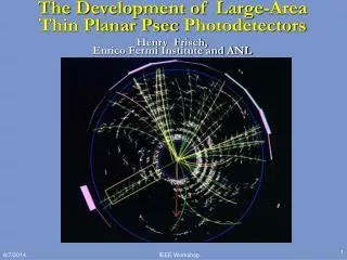
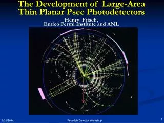
2 TeV (> 3ergs) pbar-p collisions (apologies for bluriness-ps to pdf to ppt…) Side View Beam’s Eye View ~ 10 million collisions/sec; 1 million electronics channels IBM Psec Timing
The basics of particle ID by TOF What sets the 1 psec goal for HEP? 15 GeV IBM Psec Timing
T-Tbar -> W+bW-bbar Measure transit time here (stop) W->charm sbar A real CDF Top Quark Event B-quark T-quark->W+bquark T-quark->W+bquark B-quark Fit t0 (start) from all tracks Cal. Energy From electron W->electron+neutrino Can we follow the color flow through kaons, cham, bottom? TOF!
Typical path lengths for light and electrons are set by physicaldimensions of the light collection and amplifying device. Why has 100 psec been the # for 60 yrs? These are now on the order of an inch. One inch is 100 psec. That’s what we measure- no surprise! (pictures from T. Credo) Typical Light Source (With Bounces) Typical Detection Device (With Long Path Lengths) IBM Psec Timing
Micro-photograph of Burle 25 micron tube- Greg Sellberg (Fermilab) Major advances for TOF measurements: 1. Development of MCP’s with 6-10 micron pore diameters (300 micron = 1 psec) IBM Psec Timing
Output at anode from simulation of 10 particles going through fused quartz window- T. Credo, R. Schroll Major advances for TOF measurements: Jitter on leading edge 0.86 psec 2. Ability to simulate electronics and systems to predict design performance IBM Psec Timing
Simulation with IHP Gen3 SiGe process- Fukun Tang (EFI-EDG) Major advances for TOF measurements: 3. Electronics with typical gate jitters << 1 psec IBM Psec Timing
Most Recent work- IBM 8HP SiGeprocess See talk by Fukun Tang (EFI-EDG) at Saclay wkshp http://hep.uchicago.edu/psec/conf.html Major advances for TOF measurements: 3a. Oscillator with predicted jitter ~5 femtosec (!) (basis for PLL for our 1-psec TDC) . IBM Psec Timing
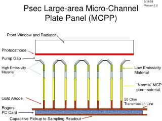
Incoming rel. particle Custom Anode with Equal-Time Transmission Lines + Capacitative. Return Solutions: Generating the signal A 2” x 2” MCP- actual thickness ~3/4” e.g. Burle (Photonis) 85022-with mods per our work Use Cherenkov light - fast Collect charge here-differential Input to 200 GHz TDC chip IBM Psec Timing
Geometry for a Collider Detector 2” by 2” MCP’s Typical Area: 28 sq m (CDF) 25 sq m (LHC) =>10K MCP’s Space in the radial direction is expensive- need a thin segmented detector Beam Axis Coil IBM Psec Timing
RF Transmission Lines • Summing smaller anode pads into 1” by 1” readout pixels • An equal time sum- make transmission lines equal propagation times • Work on leading edge- ringing not a problem for this fine segmentation Small dim. Anode Structure? IBM Psec Timing
Module divided into 4 1”x1” pixels (good for CDF,e.g) 4 differential outputs- each to a 200:1 `time stretcher’ chip (ASIC) directly on back of module Equal-Time Collector Anode Equal-time transmission-line traces to differential output pins (S and R) IBM Psec Timing
Anode Return Path Problem Current out of MCP is inherently fast- but return path depends on where in the tube the signal is, and can be long and so rise-time is variable Incoming Particle Trajectory Signal Would like to have return path be short, and located right next to signal current crossing MCP-OUT to Anode Gap IBM Psec Timing S R
Capacitive Return Path Proposal Current from MCP-OUT Return Current from anode Proposal: Decrease MCP-OUT to Anode gap and capacitively couple the return (?) IBM Psec Timing
0.250 0.160 0.070 2 in. Solving the return-path problem (?)–Add a grid to the anode layout Signal (anode) pad Return leg surface (DC biased off of ground)
Mounting electronics on back of MCP- matching Conducting Epoxy- machine deposited by Greg Sellberg (Fermilab) Temporary Solution for prototyping- can have custom anodes built and installed in MCP ($, but more so time…) dum IBM Psec Timing
Output at anode from simulation of 10 particles going through fused quartz window- T. Credo, R. Schroll End-to-End Simulation Result Jitter on leading edge 0.86 psec IBM Psec Timing
EDG’s Unique Capabilities - Harold’s Design for Readout Each module has 5 chips- 4 TDC chips (one per quadrant) and a DAQ `mother’ chip. Problems are stability, calibration, rel. phase, noise. Both chips are underway dum IBM Psec Timing
Module divided into 4 1”x1” pixels (good for CDF,e.g) Placement of chips on module 200:1 `time stretcher’ chips `DAQ’ Chip TDC, digital readout, clock distribution, calibration, housekeeping Equal-time transmission-line traces to differential output pins (S and R) IBM Psec Timing
http://hep.uchicago.edu/psec/conf.html Tang slide- March 8, 2007 Saclay France IBM Psec Timing
Tang slide- March 8, 2007 Saclay France IBM Psec Timing
Microphotograph of IHP VCO Chip(submitted through Europractice) Taken at Fermilab by Hogan – Design by Fukun Tang Affordable: <10K/shot Training Classes (Europe) But- meager technical support, libraries, … (nice folks tho- structural) IBM Psec Timing
So, switched to IBM 8HP- same 2-GHz VCO in 8HP Fukun Tang, UC IBM Psec Timing
Tang slide- March 8, 2007 Saclay France Tang slide- March 8, 2007 Saclay France Tang slide- March 8, 2007 Saclay France Tang slide- March 8, 2007 Saclay France Tang slide: http://hep.uchicago.edu/psec/conf.html
DAQ Chip- 1/module • Jakob Van Santen (4th yr undergrad) implemented the DAQ chip functionality in an Altera FPGA- tool-rich environment allowed simulation of the functionality and VHDL output • ASIC will be designed at Argonne by John Anderson and Gary Drake. • Again, simulation means one doesn’t have to do trial-and-error. IBM Psec Timing
Why is simulation essential? • Want optimized MCP/Photodetector design- complex problem in electrostatics, fast circuits, surface physics, …. • Want maximum performance without trial-and-error optimization (time, cost, performance) • At these speeds (~1 psec) cannot probe electronics • Debugging is impossible any other way. IBM Psec Timing
D Time-of-Flight Tomograph Slide from Chin-Tu Chen (UC) talk at Saclay Workshop x • Can localize source along line of flight - depends on timing resolution of detectors • Time of flight information can improve signal-to-noise in images - weighted back-projection along line-of-response (LOR) x= uncertainty in position along LOR = c .t/2 IBM Psec Timing Karp, et al, UPenn
5Mcts 5Mcts TOF 1Mcts TOF 1Mcts Our goal is 30 psec TOF+reconstruction no TOF 300 ps TOF Benefit of TOF Better image quality Faster scan time 1 Mcts 5 Mcts 10 Mcts Slide from Chin-Tu Chen (UC) talk at Saclay Workshop Karp, et al, UPenn
Back-end Processing for PET Example of a TDC for CDF we designed in Altera- has trigger logic, pipeline, pattern recognition, ….- lots of local `region-of-interest’ analysis. Speeds real-time imaging. 48 channels/chip IBM Psec Timing
Status of First (VCO) Chip Submission • Were on path for Feb 26 MOSIS submission of VCO with 8HP… • Tapeout/Details available at http://edg.uchicago.edu/psec/ • Starting on Phase-Detector; then Charge-Pump; then Const. Fraction Discriminator- long ways to go! (we are beginners…) IBM Psec Timing
SOME REFERENCES Saclay Workshop (March 8,9-07; talks on PET, Detectors, Electronics, Simulation… (in particular see talks of Chen, LeDu, Genat, Jarron,…) http://indico.cern.ch/contributionListDisplay.py?confId=13750 http://hep.uchicago.edu/psec/conf.html ANL/UC effort, links (workshops, talks,references…) http://hep.uchicago.edu/psec/ http://hep.uchicago.edu/~frisch/ J. Va’vra et al latest paper: on MCP timing: Nucl. Inst. Mett A572, 459 (2007) IBM Psec Timing
Questions (we are just starting) • What determines the ultimate limits? • Are there other techniques? (e.g. SiPM’s, …)? • Could one integrate the electronics into the MCP structure- 3D silicon (Paul Horn, Pierre Jarron)? • Will the capacitative return work? • How to calibrate the darn thing (a big system)?! • How to distribute the clock • What is the time structure of signals from crystals in PET? (photon arrival at psec level) • Can we join forces with others and go faster? IBM Psec Timing
The End- IBM Psec Timing
Backup Slides IBM Psec Timing
Slide from K.Inami (Nagoya university, Japan)- With 10mm quartz radiator +3mm quartz window Number of photons ~ 180 Time resolution = 6.2ps Intrinsic resolution ~ 4.7ps Without quartz radiator 3mm quartz window Number of photons ~ 80 Expectation ~ 20 photo-electrons Time resolution = 7.7ps http://indico.cern.ch/contributionListDisplay.py?confId=13750 Beam test result Jerry Va’vra has new similar results (see ref’s) IBM Psec Timing
Slide from Chin-Tu Chen (UC) talk at Saclay Workshop –see url in references…. Disclaimer- I know almost nothing about PET- need Chin-Tu or Patrick LeDu! PET, TOFPET & SPECT Chin-Tu Chen Chien-Min Kao, Christian Wietholt, Qingguo Xie, Yun Dong, Jeffrey Souris, Hsing-Tsuen Chen, Bill C. O’Brien-Penney, Patrick J. La Riviere, Xiaochuan Pan Department of Radiology & Committee on Medical Physics Pritzker School of Medicine & Division of Biological Sciences The University of Chicago IBM Psec Timing
PET Principle P N + e+ + n + energy E = mc2 Slide from Chin-Tu Chen (UC) talk at Saclay Workshop
30-50 may be possible (LeDu) Slide from Chin-Tu Chen (UC) talk at Saclay Workshop TOFPET DREAM 30 picosec TOF 4.5 mm LOR Resolution 10 picosec TOF 1.5 mm LOR Resolution 3 pico-sec TOF 0.45 mm LOR Resolution Histogramming No “Reconstruction” IBM Psec Timing
T-Tbar -> W+bW-bbar Measure transit time here (stop) W->charm sbar The Future- Triggering? B-quark T-quark->W+bquark T-quark->W+bquark B-quark Cal. Energy From electron W->electron+neutrino Can we follow the color flow of the partons themselves? IBM Psec Timing
Interface to Other Simulation Tools Tang slide ASCII files: Waveform time-value pair ASCII files: Waveform time-value pair Geant4/Root Tube Output Signals from Simulation Cadence Virtuoso Analog Environment Or Cadence Virtuoso AMS Environment System Simulation Results Tube Output Signals from Scope Spectre Netlist Spectre Library Spectre Netlist (Cadence Spice) Custom Chip Schematic IBM 8HP PDK IBM Psec Timing Cadence Simulator