Download
1 / 20
200 likes | 203 Views
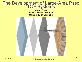
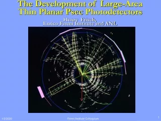
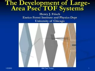
The Development of Large-Area Psec-Resolution TOF Systems. Henry Frisch Enrico Fermi Institute and Physics Dept University of Chicago. With Karen Byrum and Gary Drake (ANL); Tim Credo, Harold Sanders, and Fukun Tang (UC). What is the intrinsic limit for TOF for rel. particles?.

E N D
The Development of Large-Area Psec-Resolution TOF Systems Henry Frisch Enrico Fermi Institute and Physics Dept University of Chicago With Karen Byrum and Gary Drake (ANL); Tim Credo, Harold Sanders, and Fukun Tang (UC) HJF Arlington TX
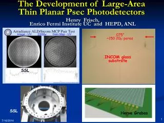
What is the intrinsic limit for TOF for rel. particles? Typical path lengths for light and electrons are set by physical dimensions of the light collection and amplifying device. These are now on the order of an inch. One inch is 100 psec. That’s what we measure- no surprise! (pictures swiped from T. Credo talk at Workshop) HJF Arlington TX
Micro-photograph of Burle 25 micron tube- Greg Sellberg (Fermilab) Major advances for TOF measurements: 1. Development of MCP’s with 6-10 micron pore diameters HJF Arlington TX
Output at anode from simulation of 10 particles going through fused quartz window- T. Credo, R. Schroll Major advances for TOF measurements: 2. Ability to simulate electronics and systems to predict design performance Jitter on leading edge 0.86 psec HJF Arlington TX
Simulation with IHP process- Fukun Tang (UC) Major advances for TOF measurements: 3. Electronics with typical gate jitters << 1 psec HJF Arlington TX
Geometry for a Collider Detector 2” by 2” MCP’s Beam Axis “r” is expensive- need a thin segmented detector Coil HJF Arlington TX
Measure track length with high precision Silicon Detectors with ~10 micron spatial resolution+ magnetic spectrometer HJF Arlington TX
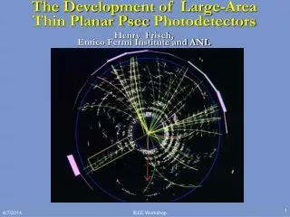
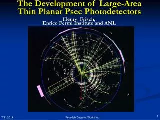
A real CDF event- r-phi view Key idea- fit t0 (start) from all tracks HJF Arlington TX
Generating the signal Use Cherenkov light - fast HJF Arlington TX
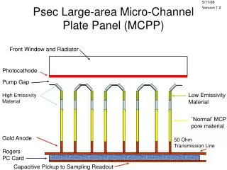
RF Transmission Lines • Summing smaller anode pads into 1” by 1” readout pixels • An equal time sum- make transmission lines equal propagation times • Work on leading edge- ringing not a problem if segmentation is fine enough (5 particles/unit rapidity/collision) Anode Structure dum HJF Arlington TX
Mounting electronics on back of MCP- matching Conducting Epoxy- machine deposited by Greg Sellberg (Fermilab) dum HJF Arlington TX
Harold’s TOF System dum HJF Arlington TX
Tang’s work in IHP design tools dum HJF Arlington TX
Tim’s Equal-Time Collector Equal time transmission-line trace 4 Output points each to a TDC chip dum HJF Arlington TX
Kaon ID in same-sign tagging in B physics (X3 in power in CDF Bs mixing analysis) • Separating b from b-bar in measuring the top mass (lessens combinatorics • Identifying csbar and udbar modes of the W to jj decays in the top mass analysis (need this once one is below 1 GeV, I belive • Separating out vertices from different collisions at the LHC in the z-t plane • Identifying photons with vertices at the LHC (requires spacial resolution and converter ahead of the TOF system • Locating the Higgs vertex in H to gamma-gamma events at the LHC (mass resolution) • Fixed target geometries- LHCb, kaon experiments, etc. • Super-B factory • Etc.- this is an area that needs work in collaboration with theorists • Non-HEP uses- PET, astro, nuclear, … (see UC workshop web page for examples) Whuffor? HJF Arlington TX
Have a simulation of Cherenkov radiation in MCP- out to anode • Have placed an order with Burle- have the 1st of 4 tubes and have a good working relationship (their good will and expertise is a major part of the effort) • Have licence and tools from IHP working on our work stations- Tang is adept and fast working with them. Looks good (so far) • Have modeled DAQ/System chip in Altera (Jakob Van Santen- 4th yr). • ANL has put together a test stand with working DAQ, identified a laser and is ordering it, has made contact with advanced accel folks, etc. • We have 3D EM frequency-domain modelling software to find the Green’s function for a duck, model the MCP/anode/collector, etc. • Harold and Tang have a good grasp of the overall system problems and scope, and have a top-level design plus details • Have found Greg Sellberg at Fermilab to offer expert precision assembly advice and help (wonderful tools and talent!). Successes HJF Arlington TX
Haven’t yet plugged in a device- all simulation • Harold and Paul Mitchell (Burle) have taught us that the hard part is the return path from MCP-OUT to the Gd • Paul also says that capacitive coupling of the signal from MCP out is visible- we need to understand the circuit. • Haven’t yet submitted a design to IHP- don’t know the realities of making chips • Have no idea, and no equipment, on how to test these chips when we get them • Have ideas, but not real ones, on how to measure device performance when we actually get them. The Hard Parts- Reality HJF Arlington TX
Last week- got Burle MK-0 (our name)- many thanks! • Paul Mitchell has done nice things- wonderful test bed for understanding HJF Arlington TX
Simulating the Electrical properties of the MCP-OUT-anode world Courtesy of Tim and Ansoft: using the HFSS package- just to show we’ve started on this.. (this is ending on a happy note- no conclusions- The End! HJF Arlington TX
Start testing the MK-0 device we have (ANL) • Understand the electrical circuit in the MCP and specify the next model (MK-I) we want • Finish the design and place the order to IHP for the 1st chip. Next Steps THE END HJF Arlington TX