Download

1 / 1
10 likes | 178 Views
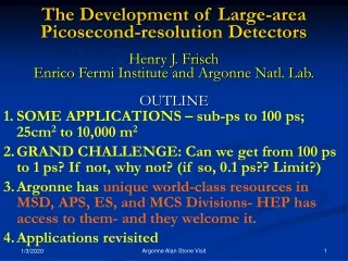
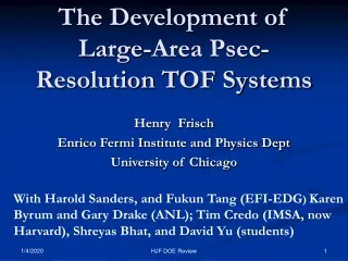
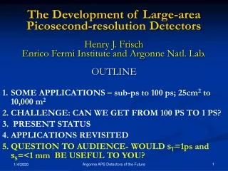
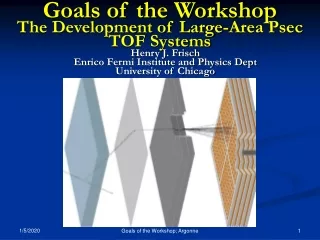
Development of Picosecond-Resolution Large-Area Time-of-Flight Systems C. Ertley 2 , J. Anderson 1 , K.Byrum 1 , G.Drake 1 , H.Frisch 2 , J. Genat 2 , H. Sanders 2 , F.Tang 2 , J. Va’vra 3. Abstract

E N D
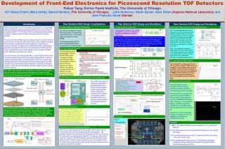
Development of Picosecond-Resolution Large-Area Time-of-Flight Systems C. Ertley2, J. Anderson1, K.Byrum1, G.Drake1, H.Frisch2, J. Genat2, H. Sanders2, F.Tang2, J. Va’vra3 Abstract The measurement of time-of-flight (TOF) of relativistic particles in high-energy colliders with psec resolution would qualitatively change the ability to identify underlying parton-level processes at future colliders or upgrades of existing detectors. We are exploring a psec-resolution TOF system using micro-channel plates (MCP's) incorporating: a source of light with sub-psec jitter, in this case Cherenkov light generated at the MCP face (i.e. no bounces), short paths for charge drift and multiplication, a low-inductance return path for the high-frequency component of the signal, optimization of the anode for charge-collection over small transverse distances, and the development of multi-channel psec-resolution custom readout electronics directly mounted on the anode assembly. Micro-Channel Plate PMT The “Mark-1” is a 1024 anode 10um pore micro-channel plate photo-multiplier tube. We are testing charge collection schemes by clamping the board to the tube and putting a conductive elastomer between them. The commercial tube is a 25um pore 64 anode tube from Photonis. It has a commercially available collection scheme. The “Mark-P” is also a 25um 64 anode tube. It has some improvements, including a new ground plane to reduce ringing. Results The “Mark-1” in the clamp with a new collection scheme. We have measured the timing properties of two MCP-PM’s from Photonis. The two 64-anode 25-micron pore tubes have a commercially available collection scheme and were used to find a limit on the timing resolution. The system was calibrated before the measurements were taken. Here we show a comparison of a red laser (635nm) and a blue laser (408nm). The discontinuity in the 635nm graph is caused by a change in attenuation. The commercial tube with a small board tying 4 anodes together. The anode side of the “Mark-1”. All of the anodes on the “Mark-P” are grounded except for the one being read out. Collection Anode The first collection scheme that was tested tied 256 anodes together. After attaching it to the Mark-1 the capacitance was measured to be 11pF using time domain reflectometry (TDR). This helped explain the slow decay time in the pulse. Laser Test Stand at Argonne A dark box was constructed at Argonne National Laboratory to test the MCP’s. It uses a Hamamatsu laser to illuminate the MCP’s and commercial electronics to measure the timing resolution and collected charge. The intrinsic jitter of the system is ~4ps and it has a resolution of 3.13ps. Histogram using the 408nm laser set at ~50pe. TDR Results: 256 = 11pF Histogram using the 635nm laser set at ~55pe. Lens to focus beam on MCP Ch 1: Commercial (5mV/div) (2ns/div) Ch 2: Mark-1 (5mV/div) 256 – pixels tied together (~26mm) 1 – pixel (~6mm) 2.29kV 1.67kV MCP 2 Mirrors to delay light. Ch 1: Yellow Ch 2: Blue The second collection scheme we tested read out groups of 16, 9, 4, and 1 anode. The board was attached to the Mark-1 and the capacitance was again measured using time domain reflectometry (TDR). The board was not correctly aligned causing loss in gain. We are currently working on a new way to attach the collection scheme to the “Mark-1”. Conclusion We have measured the timing resolution of two MCP’s using a newly assembled test-stand based on a Hamamatsu PLP-10 picosecond laser and a commercial CAMAC readout electronics system. We have developed a new collection scheme to be attached to a 1024 anode MCP. The capacitance and gain of the MCP and board were tested. X-Y Stager 50/50 Beam Splitter MCP 1 TDR Results : 1 = 1.2pF, 4 = 1.5pF, 9 = 2.3pF, 16 = 2.8pF Ch 1: Mark-1 (5mV/div) (2ns/div) Ch 2: Commercial (5mV/div) 9 – pixels tied together (~6mm) 1 – pixel (~6mm) 2.29kV 1.67kV PSEC is a collaborative effort between groups at Argonne National Laboratory1, University of Chicago2, and the Stanford Linear Accelerator Center3. Ch 1: Yellow Ch 2: Blue