Download
1 / 4
110 likes | 299 Views
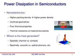
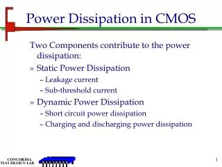
There are three components to total power dissipation in CMOS, namely: Static power dissipation Dynamic power dissipation and Short circuit power dissipation Static power dissipation is due to leakage currents. For the CMOS inverter

E N D
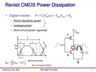
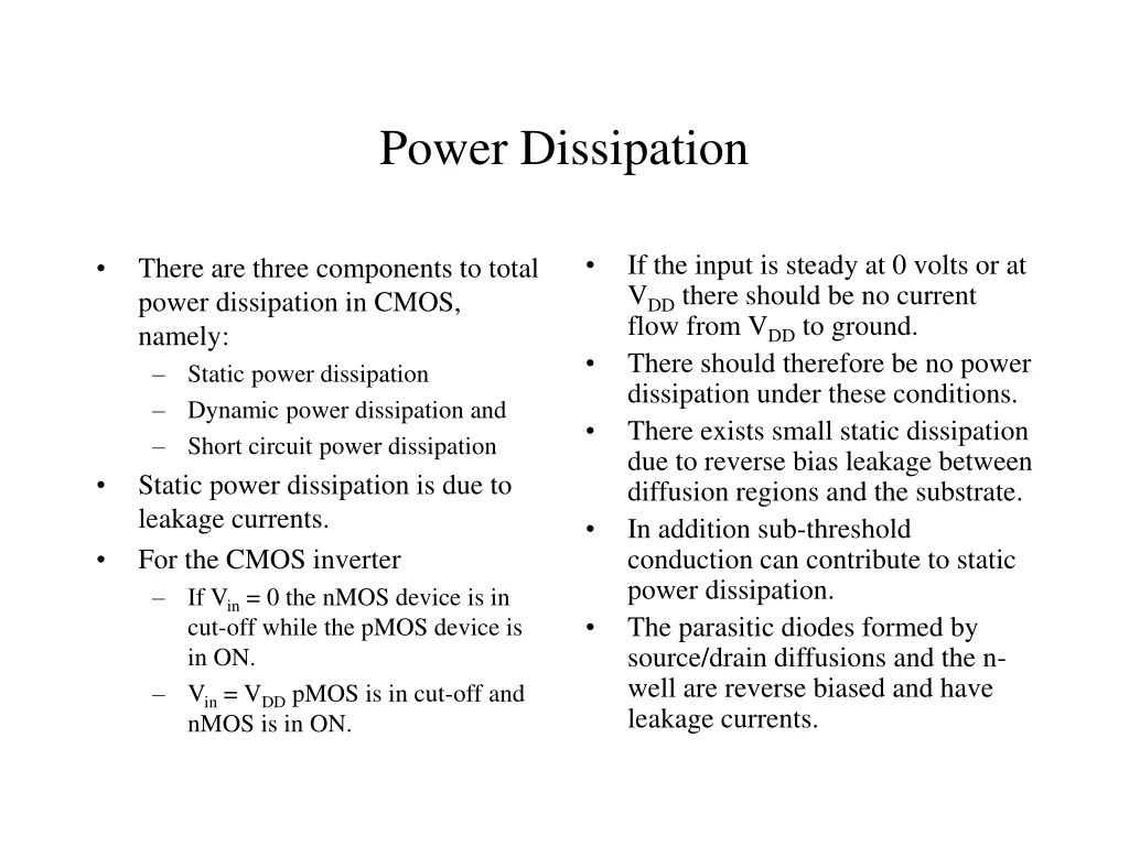
There are three components to total power dissipation in CMOS, namely: Static power dissipation Dynamic power dissipation and Short circuit power dissipation Static power dissipation is due to leakage currents. For the CMOS inverter If Vin = 0 the nMOS device is in cut-off while the pMOS device is in ON. Vin = VDD pMOS is in cut-off and nMOS is in ON. If the input is steady at 0 volts or at VDD there should be no current flow from VDD to ground. There should therefore be no power dissipation under these conditions. There exists small static dissipation due to reverse bias leakage between diffusion regions and the substrate. In addition sub-threshold conduction can contribute to static power dissipation. The parasitic diodes formed by source/drain diffusions and the n-well are reverse biased and have leakage currents. Power Dissipation
The leakage current equation is the basic diode equation: Static power is given by: Dynamic Dissipation: Short circuit current pulse from VDD to GND cause power dissipation that is dependent on the input’s rise and fall times, the load capacitance and the gate design. Slow rising and falling edges would increase the short circuit current. The capacitive load is usually the dominant term in the dynamic power analysis. Static Power Dissipation Vin VDD Vout p+ n+ n+ p+ p+ n+ N-well P-Substrate
Dynamic power can be modeled by considering a case where the rise and fall times are much smaller than the signal’s period. Average power dissipated during switching for a square-wave input (Vin), having a period tp is given by: If the n-device transient current is a step input described by: This leads to the expression: Dynamic Power Dissipation
The short-circuit power dissipation is given by Psc = Imean X VDD For an inverter without a load, but with tr = tf, the mean current is: Total power dissipation is obtained by summing the three dissipation components resulting in: Ptotal = Ps + Pd + Psc For complex circuits it is difficult to determine the power dissipated in a detailed manner. Approximations are therefore used. One approach would be to calculate the total capacitance driven by gate outputs in the circuit and estimating the activity of the circuit operating at the maximum frequency Another case involves partitioning the circuit into smaller parts to enable for accurate determination of the activity factor. Short-Circuit Dissipation