Download
1 / 34
340 likes | 516 Views
UPAC™ Combustion Control Features and Capabilities. Company Background. Present Organization Corporate Headquarters & Manufacturing: Cleveland, Ohio. Air Switch Sales, Order Processing, Customer Service: Cleveland, Ohio. Process Sales: Boynton Beach, Florida, & Cleveland, Ohio.

E N D
UPAC™ Combustion Control Features and Capabilities
Company Background Present Organization • Corporate Headquarters & Manufacturing:Cleveland, Ohio. • Air Switch Sales, Order Processing, Customer Service: Cleveland, Ohio. • Process Sales:Boynton Beach, Florida, & Cleveland, Ohio. • Engineering & Development:Cleveland, Ohio. • Combustion Product & Systems Sales:Boynton Beach, Florida. • Sales/Service Representatives:111 offices in the USA, Canada, and Mexico.
Company Background Hays Corporation was founded in 1901 by Mr. Joseph Hays. Republic Corporation joined in 1972. Thereafter, the company was known as Hays Republic Corporation. Cleveland Fuel Equipment Company was founded in 1942 by Mr. Norman Hahn. During the 1950's, the company moved to it's present location at 1111 Brookpark Road, and its name was changed to Cleveland Controls in 1958. Cleveland Controls & Hays Republic consolidated under Optimum Controls in 1984. The two corporations sold assets to UniControl Inc. during 1994. The combustion control product lines of the Hays Republic division and the Cleveland Controls division were further consolidated as Hays Cleveland during October 1996. The air switch product line remained as Cleveland Controls.
Company Background & Significant Achievements • Hays Cleveland is a pioneer developer of in-situ flue gas O2 analyzers, parallel positioning and metering systems, O2 trim systems, cross-limiting and deviation limiting strategies, and SCADA workstations. • Industries Served: Combustion Products • Fire tube and Water tube Boiler Applications • Federal & State Institutions. • Utilities: analyzers, recorders, indicator. • Process: mechanical, automotive, all private industry.
Combustion Control Product Lines • Controller Lines: • UPAC™ Universal Programmable Automation Controller • DirectLink™ • Dedicated purpose: • C-07720 Draft Control System. • C-07200 Manual/Auto Station. • R-09500 Draft Regulator (“CDR”) • Single-loop controllers. • Multiple loop controllers (C-07000AC Station Series).
UPAC™ - Introduction The new Hays Cleveland UPAC™ package provides complete facility control, monitoring and communications with the accuracy, speed and advanced capabilities expected in high-end PLC and PC automation products--at a much lower than expected investment! With UPAC™, boiler plant operations and other facility operations are fully integrated in one platform. UPAC™'s modular approach provides almost unlimited capability. Components include a touch screen, control unit and modules for analog and digital I/O.
System Overview: Hardware UPAC™ Controller CPU P/N 42026 • Multi-function platform • Modular & open architecture, both for industrial applications and for process system automation units. • Maximum connectivity guaranteed by various interface ports: RS-232, 485, Ethernet, & Fieldbus • Add Analog, Digital & RTD Modules to configure system.
System Overview: Hardware UPAC™ Controller CPU Specifications • ARM 32 bit processor • 4 Mb flash memory, 16 Mb RAM • 16Mbyte DRAM • 128Kbyte SRAM with Battery Backup • 1 CANopen master port • 1 RS232 service port • 1 Ethernet 10Mb programming and supervision port (Modbus TCP, OPC server) Optional Port configurations: • 1 RS485 port (Modbus RTU protocol, Master or Slave conf.) • 1 RS232 port (with Modbus RTU protocol, Master or Slave conf.) • 1 Profibus DP port (Slave) • 1 CANopen port (Slave)
System Overview : Hardware UPAC™ I/O Modules • Used With UPAC ™ CPU for System Applications • 8-Channel Analog Input • P/N 42008 • 8-Channel Analog Output • P/N 42014 • 16 Channel Digital Input • P/N 42012 • 16 Channel Digital Output • P/N 42016 • 4 Channel RTD or T/C input • P/N 42010
UPAC ™ Mini ControllerP/N 42062 Combines CPU with Analog & Digital I/O • CPU • 32bit processor, ARM architecture • 4mb Flash (2mb for programs) • 16mb RAM, 64kb for retentive redundant variable memory. • On-board I/O • 8 Analog Inputs • 4 Analog Outputs • 8 Digital Inputs (24v) w/ counter function (80hz max.) • 8 Digital Outputs (24v, .5A) • Interface Ports • RS232/485 Modbus RTU or ASCII • RS485 Modbus RTU • Ethernet port with Modbus TCP Server • Other Mini controller units available
System Overview : Hardware UPAC™ Touch Screen HMI • 12.1” color TFT screen Standard • Other sizes available • 800x600 pixel resolution • Cirrus Logic 32-bit processor • 600:1 Contrast Ratio • 128kb SRAM w/ battery backup • NEMA 4 rated.
Software – OpenPCS • IEC 61131-3 Programming • Instruction List • Structured Text • Sequential Function Chart • Function Block diagram • Ladder diagram • Standard IEC Function library • Hays Cleveland Custom library • Online Debugging • Offline Simulation
Software – Indusoft Webstudio HMI software package • Web interface that allows you to visualize screens in a Web browser • Platform-independent application • Online, remote application management and configuration (download/upload, commands, system and network diagnostics, and debugging) • Screen and object password-protected run-time security • Full-featured objects and dynamics with customizable object properties such as bar graphs, color, resizing, position, rotation, hide/unhide, commands, hyperlinks, and text input/output;
Connectivity Ethernet modbus TCP/IP communications between HMI, Controller and SCADA CanOpen protocol to modules RS232 serial & RS485 modbus
Connectivity Standard Communications to SCADA is through Modbus TCP/IP. Other solutions such as gateways can be provided for interfacing with building management systems such as LonWorks, BacNet and Metasys Network Switch or Gateway Modbus TCP/IP Communications Plant Master SCADA or Building Management System Modbus TCP/IP Communications Boiler 1 Boiler 2 Boiler 3 Boiler 4
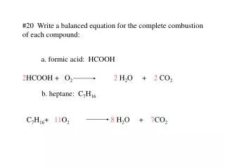
Applications - Combustion Control UPAC™ enhances operator awareness, improving efficiency and safety throughout the facility. It can control more than 10 devices for applications ranging from boiler combustion control to DA tank and condensate tank control. For example, in a typical parallel positioning application with O2 trim and boiler efficiency monitoring, UPAC™ would control the gas and oil valves; FD damper and FD damper VFD with by-pass; FGR, feed water control valve, draft damper and boiler feed water pump VFD.
Applications • Single Package Plant Automation & Control • Linkageless Servomotor Control • Single Point to Full Metering Combustion Control • O2 Trim Control • Advanced PID Control • Boiler Lead-Lag Sequencing • Pump Sequencing • Feedwater Control • Surge Tank control • BMS Interface • Flow & Efficiency Computations • Economizer Bypass Control
Plant Wide Control Enhanced Plant wide control with the UPAC™ can include: • Plant master operations • DA & Condensate Tank level control • Feedwater pump sequencing • Fuel Oil Tank level monitoring and provide one central location for operator viewing and control.
Boiler Combustion Control A typical parallel positioning application with O2 trim and boiler efficiency monitoring, UPAC™ controls the gas and oil valves; FD damper and FD damper VFD with by-pass; FGR, feed water control valve, draft damper and boiler feed water pump VFD, all while monitoring the economizer IN and OUT temperatures and calculating overall boiler efficiency.
Boiler Control Operations (cont.) UPAC™ parallel positioning and metering applications use the same Hays Cleveland UL 1998 Certified Strategies as our AC Station™ hardware platforms. For safety, both cross-limiting and deviation-limiting logic as well as actuator failure detection are employed in these strategies to prevent the occurrence of low excess air.
Control Screen Examples – Overview screen ( Home button) The Home button will display the Boiler Overview screen which gives the operator the current status of: • Temperatures • Flows • Firing rates • Flame safeguard status • Servo positions
Control Screen Examples – LOCAL BOILER MASTER The Local pressure master screen is present on both boiler controls and allows for either manual control from the operator, or automatic control based on boiler pressure. This loop is only active when “LOCAL MASTER” is highlighted below the bargraph. This is normally due to a plant master signal failure.
Control Screen Examples – BOILER SUB-MASTER From the Pop-up control, touching the “OIL” button brings up the boiler submaster screen. This screen gives the operator an overview of the fuel/air position of the boiler. By touching the “Auto/Man” button on either the “Submaster” or “Oxygen trim” loop allows the operator to take manual control of that particular loop. The Fuel /Air auto/manual buttons are disabled while logged in as operator.
Control Screen Examples – FEEDWATER CONTROL Touching the “FEEDWATER” button on the pop-up menu will display the feedwater control loop. This screen provides the operator with the current status of the: • Boiler drum level • Steam flow • Feedwater flow • Actuator position The operator can also take manual control of the feedwater by touching the auto/man button and specifying a valve percentage.
Control Screen Examples – DRAFT CONTROL Pressing the “DRAFT” button on the operator pop-up menu will display the Draft Control screen. On this screen you will find • Draft control setpoint • Actual/current Draft value • Draft Actuator Position • Auto/Manual Status While logged in as Operator, you can place the draft control loop in either auto or manual. While in manual mode, the operator can select the position of draft actuator to be held at.
Control Screen Examples – TREND SCREENS ( ) The “Trend” icon on the main menu will bring up a list of available trends for display. The format for each trend screen is the same, with the large trend graphic, ranges to the left side, and the legend for each line at the bottom of the screen. The check boxes in the legend area will turn on or off that particular line.
Control Screen Examples – HISTORICAL ALARMS ( ) The historical alarm icon will display all the alarms from the last seven days that the UPAC has monitored. This screen will give you the date and time of the alarm as well as the current status. The legend at the bottom of the screen is the color legend to help identify the state of the alarm, whether it has been acknowledged (green) or has returned to normal (blue). This color code also applies to the Alarm Pop-up display.
Control Screen Examples – Plant Master Control loop The Plant Master Screen is the main screen that should be displayed most of the time. At a glance, the user can see the header pressure, master loading demand signal to all the boilers, header steam flow, and the outside air temp.
Control Screen Examples – Feedwater Pump Sequencers The Feedwater Pump screen provides the user with information regarding the two-pump sequencer for boiler #4 feedwater, and the three pump sequencer for boilers #1,2,& 3. Included for each set of sequencer controls are: • Auto/Manual for each pump • Lead pump select • Lead and lag pumps cut-in (On) and cut-out (Off) points.
Control Screen Examples – DA Tank Control There are individual screens for each DA Tank. The corresponding screen will give the user the current tank level, tank water temperature, and the fill valve position.
Control Screen Examples – Condensate Tank Control The Condensate tank screen accessible from the operator pop-up menu gives the user an overview of condensate system. This consists of: • Makeup water flow • Return water flow • Transfer pumps and sequencer status • Tank level, and • Fill valve position (If installed).
Control Screen Examples – Fuel Oil Tank Screen The control system monitors the status of each fuel oil storage tank. The individual tank levels, high and low level alarms are provided from the Omntec fuel oil monitoring system and are displayed on the Master UPAC control. Access to this screen is from the operator pop-up menu, “FUEL OIL TANKS” button.
Engineering Services We program each UPAC™ system for a specific application. Typical packages include the auxiliary instrumentation necessary for a complete system: level and pressure transmitters, flow meters and actuators, and an optional SCADA workstation. Complete wiring and system schematics are provided.
SUMMARY We greatly appreciate the opportunity to present this material to you. Please contact the Sales Department (561-734-9400) or your local Hays Cleveland Representative for quotations, specifications and sales support.