Supersonic Combustion
Supersonic Combustion. Theresita Buhler Sara Esparza Cesar Olmedo. Purpose & Goals Introduction to combustion Engine parameters Jet Engine Ramjet Scramjet Jet Engine vs. Scramjet Model Reference stations Analytical approach Compressible flow Shockwaves Inlet: Diffuser design

Supersonic Combustion
E N D
Presentation Transcript
NASA Grant URC NCC NNX08BA44A Supersonic Combustion Theresita Buhler Sara Esparza Cesar Olmedo
NASA Grant URC NCC NNX08BA44A Purpose & Goals Introduction to combustion Engine parameters Jet Engine Ramjet Scramjet Jet Engine vs. Scramjet Model Reference stations Analytical approach Compressible flow Shockwaves Inlet: Diffuser design COSMOSWorks design Engine: Cowl design Combustion schemes & fuels Exhaust: Expansion Prototype design Materials Design Specifications Installation in the wind tunnel Location Fuel lines and ignition wires Hydrogen safety History Cost Acknowledgements Questions Supersonic Outline
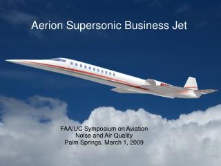
NASA Grant URC NCC NNX08BA44A Hypersonic Vehicle • High speed travel • Commercial flight • Reaction engines • Circumnavigation in four hours • NASA Goals • Global reach vehicle • Reduced emissions • Challenges • Shockwaves • High heat • Combustion instability • Flight direction control NASA X-43 Vehicle NASA X-51 Testing
NASA Grant URC NCC NNX08BA44A Combustion • Fuel • Air • Heat • High pressure flow, at high compression • Quickly changing conditions • Temperature difficulties • Frictional heating • High forced convection • Highly turbulent • Shock
NASA Grant URC NCC NNX08BA44A Engine Parameters Fit engine to aerospace system Jet Engines – Low orbit, max Mach 3 Ramjets – High altitude, supersonic flight, subsonic combustion Scramjets – High altitude, hypersonic flight, supersonic combustion
NASA Grant URC NCC NNX08BA44A Jet Engines • Combustion chamber • Introduce fuel • House combustion • Turbine blades • Capture expansion of exhaust gases • Inlet design • Feed air into chamber • Compressor blades • Increase pressure of flow
NASA Grant URC NCC NNX08BA44A Ramjet • Vehicle travels at supersonic speed • Simplest air-breathing engine • No moving parts • Compression of intake achieved by supersonic flow – inlet speed reduction • Shockwave system • Relatively low velocity • Combustions at subsonic speeds • Very high reduction in speed • High drag • High fuel consumption • Temperature at 3000 K (4940°F) • Diffuser • Exit plane contracts • Exhaust at supersonic speed • Travel: M = 3 • Combustion: M= 0.3
NASA Grant URC NCC NNX08BA44A Scramjet • Hypersonic flight • No moving parts • Combustion at Supersonic speed • Flow ignites supersonically • Fuel injection into supersonic air stream • Steer clear of shock waves • Is Aerodynamically challenged
NASA Grant URC NCC NNX08BA44A ScramjetBoeing
NASA Grant URC NCC NNX08BA44A Then and Now
NASA Grant URC NCC NNX08BA44A What is Supersonic Combustion Combustion maintained at supersonic speed How is it achieved? Design Shockwave Fuel Injector Detonation Combustion
NASA Grant URC NCC NNX08BA44A Oblique shocks Mach number decreases Pressure, temperature, and density increase Attached to vehicle Normal shocks Mach number decreases Pressure, temperature, and density increase Creates subsonic region in front of nose Detached Shock Waves
NASA Grant URC NCC NNX08BA44A Oblique shock Mach number decreases Pressure, temperature, and density increase Expansion wave Mach number increases Pressure, temperature, and density decrease Shock Waves
NASA Grant URC NCC NNX08BA44A Diffuser Development • Wind tunnel specifications • Inlet speed • Mach 4.5 • Cross-sectional area • 6 x 6 in • Length of test section • 10 in
NASA Grant URC NCC NNX08BA44A Design of Diffuser • Initial design of diffuser • Use manifold design to introduce fuel • Diffuser was designed in to two separate pieces Goal Seek 18° 28.29° 19.67°
NASA Grant URC NCC NNX08BA44A Design of Diffuser • Top part of the diffuser • Has machined holes for fuel and ignition wires. • Also four holes for securing the base of the diffuser
NASA Grant URC NCC NNX08BA44A Design of Diffuser
NASA Grant URC NCC NNX08BA44A 2D Shockwaves
NASA Grant URC NCC NNX08BA44A Inefficient Designs Bow Shock – Cowl Interference Oblique Shock – Cowl Spillage
NASA Grant URC NCC NNX08BA44A Cosmo Flowork Analysis
NASA Grant URC NCC NNX08BA44A Cosmos Flowork Analysis Velocity Profile Mach Speed Profile
NASA Grant URC NCC NNX08BA44A Cosmos Flowork Analysis Pressure Contours Inlet Mach = 4.5
NASA Grant URC NCC NNX08BA44A Cosmos Flowork Analysis Temperature Contours Inlet Mach = 4.5
NASA Grant URC NCC NNX08BA44A Cosmos Flowork Analysis
NASA Grant URC NCC NNX08BA44A Ramp Fuel Injections Ramped Outward Ramped Inward
NASA Grant URC NCC NNX08BA44A Cosmos Flowork Analysis
NASA Grant URC NCC NNX08BA44A Cosmos Flowork Analysis
NASA Grant URC NCC NNX08BA44A Cosmos Flowork Analysis
NASA Grant URC NCC NNX08BA44A Cosmos Flowork Analysis
NASA Grant URC NCC NNX08BA44A Combustion • Combustion Stoichiometry • Ideal fuel/ air ratio • Recommended fuel for scramjets • Hydrogen • Methane • Ethane • Hexane • Octane • Only Oxidizer is Air • Maximum combustion temperature • Hydrocarbon atoms are mixed with air so • Hydrogen atoms form water • Oxygen atoms form carbon dioxide • Most common fuel for scramjets • Hydrogen • In scramjets, combustion is often incomplete due to the very short combustion period. • Equivalence ratio • Should range from .2 -2.0 for combustion to occur with a useful time scale • Lean mixture ratio below 1 • Rich mixture ratio above 1
NASA Grant URC NCC NNX08BA44A CombustionParallel Mixing Fuel- Air Mixing at mach speeds Gas phase chemical reaction occurs by the exchange of atoms between molecules as a results of molecular collisions. The fuel and air must be mixed at near-stoichiometric proportions before combustion can occur Parallel Mixing of Fuel- Air U1 Mixing Layer δm U2
NASA Grant URC NCC NNX08BA44A CombustionParallel Mixing • Zero shear mixing • Both air and fuel velocities are equal • Shear stress doesn’t exist between streams • Coflow occurs • Lateral transport • Occurs by molecular diffusion • At fuel – air interface • No momentum or vorticity transfer • Axial development of cross –stream profiles of air mole fraction YA in Zero shear (U1=U2) • Fuel Mole fraction Profile is YF=1-YA • Mirror Image Ya Ya U1 δm U2
NASA Grant URC NCC NNX08BA44A CombustionParallel Mixing • Molecular diffusion • Fick’s Law • Air molecular transport rate into fuel • Proportional to the interfacial area times the local concentration gradient. • Proportionality constant • DFA, = molecular diffusivity • Where DFA*ρ is approximately equal to molecular viscosity μ for most gases Ya Ya U1 δm U2
NASA Grant URC NCC NNX08BA44A CombustionParallel Mixing • Fick’s law for diffusion
NASA Grant URC NCC NNX08BA44A Combustion Parallel Mixing Ya Ya U1 δm U2
NASA Grant URC NCC NNX08BA44A y B1 Ya Ya U1 x δm U2 -B2 B1+B2 X=Lm X=0 Combustion Parallel Mixing • Steepest concentration gradient at x = 0 • Mixing layer reaches the wall at x=Lm the air mole fraction still varies from 1.0 at y=B1 and 0 at y= -B2 • More mixing is needed • 2Lm is recommended by experiment • enables complete micro-mixing
NASA Grant URC NCC NNX08BA44A y B1 Ya Ya U1 x δm U2 -B2 B1+B2 X=Lm X=0 Combustion Parallel Mixing Mixing layer thickness equation Estimate injector height, B1+B2=B to reduce mixing length, Lm
NASA Grant URC NCC NNX08BA44A Combustion Parallel Mixing Manifolding idea Multiple inlets Reduce mixing length Tradeoff: Inefficient design Adds bulk and volume Air δm B Fuel δm Air Fuel
NASA Grant URC NCC NNX08BA44A Combustion Laminar Shear Mixing • Molecular diffusion alone cannot meet the requirements of rapid lateral mixing in supersonic flow • Solution shear layer between both layers • U1>U2 , Uc=0.5(U1+U2 ) • Velocity ratio r =(U1/U2 ) • Velocity Difference Δ U= (U1-U2 ) μ: dynamic viscosity ν: kinematic viscosity
NASA Grant URC NCC NNX08BA44A Combustion Turbulent shear mixing • As we further increase the velocity difference delta U • Shear stress causes the periodic formation of large vortices • The vortex sheet between the two streams rolls up and engulfs fluid from both streams and stretches the mixant interface. • Stretching of the mixant interface increases the interfacial area and steepens the concentration gradients • Shear mixing increases molecular diffusion
NASA Grant URC NCC NNX08BA44A Combustion Turbulent shear mixing Fuel wave Fuel vortex Micro-mixing
NASA Grant URC NCC NNX08BA44A CombustionTurbulent Shear Mixing • Mean velocity profile combines • Prandtl’s number • Turbulent kinematic viscosity • Time average characteristics of turbulent shear Micro-mixing Fuel wave Fuel vortex
NASA Grant URC NCC NNX08BA44A CombustionTurbulent Shear Mixing Shear layer width – Two methods Local shear layer width for turbulent shear mixing Recent research Cδ is a experimental constant
NASA Grant URC NCC NNX08BA44A CombustionTurbulent Shear Mixing • Density effects on shear layer growth – compressible flow • Based on constant but different densities • A density ratio, s, is derived • s can be calculated once stagnation pressure and stream velocities are known
NASA Grant URC NCC NNX08BA44A CombustionTurbulent Shear Mixing • Convective velocity for the vortex structures • With compressible flow using isentropic stagnation density equation changes to
NASA Grant URC NCC NNX08BA44A CombustionTurbulent Shear Mixing • Density correct expression for shear layer growth including compressibility effects
NASA Grant URC NCC NNX08BA44A CombustionTurbulent Shear Mixing Only applies to box cowl
NASA Grant URC NCC NNX08BA44A Fuel CombustionTurbulent Shear Mixing Based on what we know the angle of our hydrogen injection should be To produce a hydrogen rich mixture Lm, F air Lm, A
NASA Grant URC NCC NNX08BA44A Mixing Controlled Combustion High mixture temperature High reaction rates Limiting feature: mixing Reaction Rate Controlled Low mixture temperature Adequate mixing Limiting feature: reaction rates Rate of heat release Diffusion Combustion
NASA Grant URC NCC NNX08BA44A Diffusion Combustion • Symmetric flame • Stoichiometric ratio • Varies across flame • Flame center • Highest temperature, fuel • Air lost around edges