
Chapter 7
Chapter 8. Chapter 5. Chapter 7. IKE UDP. Figure 5.1 Relative Location of Security Facilities in the TCP/IP Protocol Stack. Excerpt from Rescorla “SSL and TLS” He has described a “simple messaging system” similar to PGP, then he goes on:.

Chapter 7
E N D
Presentation Transcript
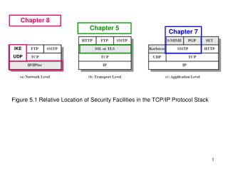
Chapter 8 Chapter 5 Chapter 7 IKE UDP Figure 5.1 Relative Location of Security Facilities in the TCP/IP Protocol Stack
Excerpt from Rescorla “SSL and TLS” He has described a “simple messaging system” similar to PGP, then he goes on: The system we’ve just described works pretty well if all we’re doing is sending simple messages around, as with e-mail, but it rapidly becomes inadequate if what we want is to have a communications channel over which we can pass arbitrary messages. We’d like to be able to establish a set of secret keys that we could use for an entire connection. This would let us avoid doing expensive public key operations for every packet, which is especially important in interactive applications where each keystroke might generate a packet. A typical design for such a system is to have a handshake phase where Alice and Bob authenticate each other and establish keys. Then they move on to a data transfer phase where they use those keys to actually transmit the data they’re interested in. We’ll see this in our study of IPSec. The handshake phase protocol is called Internet Key Exchange (IKE) In Chapter 8 Stallings will leave the handshake phase until last.
Chapter 8 – IP Security 8.1 IP Security Overview Applications of IPSec ► Secure branch office connectivity over the Internet (“Virtual Private Network”) ► Secure remote access over the Internet (traveling employees and telecommuters) ► Extranet and Intranet connectivity with partners ► Enhancing E-commerce security (B to B)
* VPN telecommuter * BHM * ATL VPN Figure 8.1 An IP Security Scenario * We see that IPsec inserts new headers between the IP header and the IP payload
Benefits of IPsec ► When IPSec implemented in firewall, all traffic crossing boundary can be protected, but internal traffic does not suffer overhead of security-related processing ► IPsec in firewall is resistant to bypass (provided firewall is only means of access) ► IPsec transparent to applications ► IPsec can be transparent to end users ("tunnel mode") ► IPsec can provide security for end users if needed ("transport mode") Routing Applications Protection of routing updates (recall RIP)
IPsec Documents There are three basic IPsec protocols: ► Authentication Header (AH): AH is an extension header to provide message authentication. Because some authentication is also (optionally) providedin ESP, AH is no longer used much and in the 4th edition Stallings has deleted the section on AH that was in previous editions of the book. However, he continues to refer to AH in several places, so you need to know that it exists. ► Encapsulating Security Payload (ESP): this provides encryption and optional authentication of messages. ► Internet Key Exchange (IKE): This protocol governs the preliminary handshake phase.
IPsec Services ► Access control ► Connectionless integrity ► Data origin authentication ► Rejection of replayed packets ► Confidentiality (encryption) ► Traffic flow confidentiality (in tunnel mode)
Transport and Tunnel Modes – overview Transport Mode provides protection primarily for upper-layer protocols – that is, for the IP datagram payload. Transport mode is typically used in end-to-end communication between two hosts. Tunnel Mode extends protection to the entire datagram, by encapsulating it in a new “outer” datagram. Tunnel mode is typically used in communication between two routers (must be used if a router is involved).
You will see this in lab session #2 Tunnel Mode
8.2 IP Security Policy Security Associations (SA) (page 276/7) – established during handshake ► SA is a one-way relationship between a sender A and a receiver B that specifies security services to be applied to a subset of traffic from A to B ► if a peer relationship is desired, we need at least two SAs ► a single SA specifies authentication (AH) XOR encryption (ESP) so we may need 4 SA’s for two-way traffic between A and B
Focus on an outbound IP datagram crossing the boundary between an intranet and the Internet. How is it decided what security processes are applied to this datagram? This is a policy decision by administration. The decision for each category of traffic is entered into a Security Policy Database. The menu of available processes is collected into a Security Association Database. Adopt 2-step process - entries in the Security Policy Database point to entries in the Security Association Database.
* IP destination address * SPI Information in the SA database has been agreed to by sender and receiver during the preliminary handshake phase (IKE).
“A security association is uniquely identified by three parameters: ► Security Parameters Index (SPI) ► IP address of destination endpoint of SA ► IPSec protocol (AH XOR ESP)” * IP destination address * SPI
Summary of relationship between SPD, IKE, and SAD: Note that SA must first be established between the two IKEs
Security Association (SA) Example: Handshaking over secure inter-IKE channel to establish ESP SA from source BHM to destination ATL CLT BHM Want SA ATL Chooses SPI = 1235 IKE: negotiate algorithms, develop keys, authenticate participants ATL This SA uniquely identified by AH XOR ESP = ESP SA destination = ATL SPI = ??? ATL Chooses SPI = 1234 SPI is unique, local to destination endpoint of SA 1234 SA BHM → ATL established
Note that BYPASS IPsec is a possible policy for non-sensitive traffic that requires no security processing.
Now consider incoming traffic (page 280/1) IP datagram arrives: 51 AH header DATA PROTOCOL field = 51 reveals data processed with AH PROTOCOL field = 50 reveals data processed with ESP We’ll see that the IPsec header includes the SPI
Incoming Traffic – contd. Consider an IPsec datagram arriving at ATL over our example SA BHM This SA uniquely identified by AH XOR ESP = ESP SA destination = ATL SPI = ??? ATL ATL knows that it is ATL! The other two parameters are readily available to ATL in the incoming datagram headers 1234 Search of incoming SPD is not necessary: ATL can index into SAD
Index PROTOCOL = 50 or 51 There may be incoming datagrams that were not subjected to IPsec processing – search of incoming SPD needed to detect intruders.
8.3 Encapsulating Security Payload H Initialization Vector P T Optional Integrity Check Value (MAC) Figure 8.5(a) ESP Packet Format
Anti-Replay Service Figure 8.6 Anti-replay Mechanism
ESP in transport mode Alice Bob End-to-end encryption ESP in transport mode conceals what Alice is saying to Bob, but not that Alice and Bob are communicating.
ESP in tunnel mode Alice VPN Bob ESP in tunnel mode over the VPN also conceals the fact that Alice is talking to Bob
Alice VPN Bob
Scope of ESP encryption and authentication Original datagram Protocol = 6 ESP authentication does not extend to the IP header ESP in transport mode Protocol = 50 Next = 6 ESP in tunnel mode Next = 4 Protocol = 50
8.4 Combining Security Associations Since a single SA is tightly focused, it may be necessary to combine more then one to get the desired protection [the new standard, RFC 4301 drops the term security associationbundle ]. For example, the previous slide noted that ESP authentication does not extend to the IP datagram header. AP does authenticate the “immutable” (unchanging) fields in the datagram header, so we may need both ESP and AH. The SAs may terminate at different endpoints, or at the same endpoint. There are two way to combine SAs: ► Transport adjacency - apply more than one protocol to a given IP datagram example: ESP, followed by AH ► tunneling (possibly iterated) - encapsulation of one datagram inside another
Authentication plus confidentiality, using Transport Adjacency This is simple, but undesirable, because it authenticates the ciphertext
Authentication plus confidentiality, using tunneling. First, apply AH in transport mode: Recall ESP in tunnel mode: With this scheme, AH authenticates the plaintext
Basic Combinations of Security Associations End-to-End Security: Already discussed, and you will see it in lab session #2, section 9
Secure transmission over Internet VPN You will see this in lab session #2, section 5
End-to-End Security over VPN: You will see this in lab session #2, section 10
Traveling salesperson or telecommuter communicating over Internet
8.5 Internet Key Exchange Although Stallings presents this at the end of Chapter 8, it actually has to occur before data can be exchanged securely. The default key automated key management protocol for IPSec consists of two parts (p293): ► Oakley Key Exchange Protocol (development of Diffie-Hellman) Discuss this next ► Internet Security Association and Key Management Protocol provides a framework for negotiation of security attributes Defer to page 296
Key Determination Protocol(Oakley) Recall Diffie-Hellman Key Exchange Protocol: K is the session key that will be used for symmetric encryption of data transmitted. Global public parameters q (modulus) and α (generator) already agreed. Y is public key, X is private key.
Diffie-Hellman Advantages: ► secret keys created only when needed ► exchange requires no pre-existing infrastructure Disadvantages: ► no authentication of participants ► subject to (wo)man-in-the-middle attacks ► computationally intensive subject to “clogging attacks” (next slide) ► vulnerable to replay attack (more later)
Clogging attack: Darth masquerades as A (trusted by B), sends YA, triggering extensive computation by B.
Features of IKE Key Determination (p294) 1. It uses Cookies to thwart clogging attacks 2. The two parties negotiate use of a group (the global parameters q and α) 3. It uses Nonces protect against replay attack 4. It enables Diffie-Hellman public key exchange 5. It authenticates the participants (protects against man-in-the-middle attacks)
Cookie requirements (to defend against clogging attacks): 1. Cookie must depend on the two specific parties. 2. Impossible for anyone other than the issuing entity to generate a cookie that will be accepted by that entity (must use local non-shared secret information in generation and verification) 3. Generation and verification methods must be fast. Recommendation for cookies: Perform a hash over the source and destination IP addresses, the TCP/UDP source and destination ports, and a locally-generated secret (not shared) value. Note: ►cookies are not time-dependent ► IKE cookies are not the same as HTTP cookies.
Clogging attempt by Darth, from spoofed IP address of A Darth can force B to generate ACKs, but not to compute DH keys
But cookies, not being time-dependent, do not protect against a replay attack 1 3 Darth copies messages 1 and 3
Replay Attack: Darth has copied message 1 and after A and B have finished their exchange Darth re-sends message 1 to B. 1 3 B thinks this initiates a new exchange and responds as before, sending message 2 to A; A recognizes cookA, but knows she didn’t initiate a new exchange, so she ignores this as a delayed duplicate. Darth has also copied message 3 and now re-sends it to B. B recognizes his own cookie, concludes that the exchange is genuine and computes YB and K – wasted computation.
A nonce is a number used only once. 1 Replay attack (replay messages 1 and 3) fails, because B knows he has seen the nonce nA before.
IKE key determination refers to a group, which is essentially values of the global parameters modulus q and generator α. Standard groups: ► 1. modular exponentiation (MODP) with 768-bit modulus, α = 2 ► 2. modular exponentiation with 1024-bit modulus, α = 2 ► 5. modular exponentiation with 1536-bit modulus, α = 2 ► two elliptic curve groups (omit)
Authentication of Participants As usual, we have to authenticate the participants. On page 295/6 Stallings states that three methods can be used with IKE key determination (Oakley.) ► Digital signatures ► Public-Key encryption - encrypt with sender private key The first two methods appear to be the same ► symmetric-key encryption – manual exchange of secret key
Second part of IKE/Oakley: IKE is an application layer protocol, using UDP to carry messages. IKE IPsec ISAKMP refers to Initiator and Responder, since it is controlling Layer 3, where a client-server situation does not exist. Initiator and Responder are peers, both using UDP port 500. I think of IKE as a puppeteer, operating above the stage, pulling the strings that set the dials and switches at the IP layer.
There are now two versions of IPsec/IKE. Stallings’ pages 294-300 cover IKE version 2, but since we have version 1 in the lab we’ll substitute a handout. Application Layer (5) IP Layer (3) Although this figure refers to IKEv2 and IPsecv3, the basic structure is correct for us.
We have seen that before a pair of security gateways can exchange user data protected by IPsec, they must complete a preliminary handshake, the Internet Key Exchange. During the handshake they authenticate each other and establish algorithms and keys that will be used in subsequent user data transfer. IKE itself has two phases: ► phase 1: a secure channel, the IKE Security Association pair is set up between the two security gateways ► phase 2: the two gateways use this channel to negotiate safely one or more IPsec SA pairs that will be used to protect transfer of user data between the two intranets Both phases must be complete before user data can flow
IKE provides two items: ► a collection of message formats ► standard sequences of these messages to accomplish specific objectives We consider these in order.


