8 Bit Gray Code Converter
2. Agenda. AbstractIntroductionWhy 8-bit gray code?Theory of 8-bit gray code encoderBackground InformationSummary of ResultsProject (Experimental) DetailsResultsCost AnalysisConclusions. 3. Abstract. 8 bit Gray Code Converter converts regular binary number to Gray code numbersBinary ? Gra

8 Bit Gray Code Converter
E N D
Presentation Transcript
1. 1 8 � Bit Gray Code Converter Murad Amer
Umair Sophie
Raymond Vengersammy
Advisor: Dr. David Parent
May 11, 2005
2. 2 Agenda Abstract
Introduction
Why 8-bit gray code?
Theory of 8-bit gray code encoder
Background Information
Summary of Results
Project (Experimental) Details
Results
Cost Analysis
Conclusions
3. 3 Abstract 8 bit Gray Code Converter converts regular binary number to Gray code numbers
Binary ? Gray
Operates at a clock frequency of 200 MHz
Power: 6mW
Area: 265mm x 150mm
DFF
MS-Latch: Wn = 1.50, 1.65um, Wp = 2.55, 2.70 um SL-Latch: Wn = 1.95, 1.65 um, Wp = 1.65, 2.70 um
XOR
AOI: Wn = 1.5um, Wp = 2.7um
INV: Wn = 1.5um, Wp = 2.7um
4. 4 Introduction Why the Binary Gray Code Converter???
First of all, it applies many of the concepts from the class and lecture (EE-166)
BGCC, is applied in many applications
This project converts a series of binary numbers to gray code numbers with the use of XOR gates and DFF�s
5. 5 Project Summary Picked an initial load capacitance (Cload)
Partitioned the circuit into different propagation delay times according to gate/device requirements
Created the schematic, symbol and layout for each type of gate (XOR, MUX-DFF)
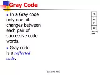
Limits the amount of error that can occur when several bits change between numbers
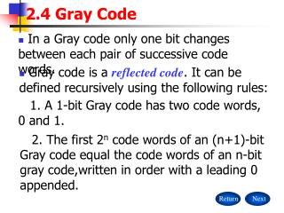
6. 6 Conversion Decimal Binary Gray Code
0 0000 0000
1 0001 0001
2 0010 0011
3 0011 0010
7. 7 Project Details Binary to Gray
Uniform cell heights of 30 �m
7 XOR gates
16 Mux based D-Flip Flops
8. 8 Longest Path Calculations
9. 9 Schematic (DFF)
10. 10 Layout ( DFF)
11. 11 Simulations (DFF)
12. 12 Schematic (XOR)
13. 13 Layout ( XOR)
14. 14 Gray Code Schematic
15. 15 Gray Code Layout
16. 16 Verification
17. 17 Gray Code Simulation
18. 18 Cost Analysis We Spent Many Hours on this Project
Verifying logic = 10 hrs
Verifying timing = 30 hrs
Layout = 25 hrs
Post extracted timing = 5 hrs
19. 19 Lessons Learned START EARLY!
FOCUS in class
START EARLY!!
Utilize other students in the class
START EARLY!!!
Work as a TEAM efficiently
START EARLY!!!!
20. 20 Summary This Project explained the Fundamentals of EE-166
Taught us the Ins - and - Outs of basic Design
Less Power Used, Less Area Used
Met Specifications
21. 21 Acknowledgements Thanks to our families for putting up with us for not being home.
Thanks to Cadence Design Systems for the VLSI lab
Thanks to Synopsys for Software donation
Dr. David Parent
Thanks to the janitors/security for letting us spend late hours in the labs.