8 – Bit Gray Code Converter
8 – Bit Gray Code Converter. Murad Amer Umair Sophie Raymond Vengersammy Advisor: Dr. David Parent May 11, 2005. Agenda. Abstract Introduction Why 8-bit gray code? Theory of 8-bit gray code encoder Background Information Summary of Results Project (Experimental) Details Results

8 – Bit Gray Code Converter
E N D
Presentation Transcript
8 – Bit Gray Code Converter Murad Amer Umair Sophie Raymond Vengersammy Advisor: Dr. David Parent May 11, 2005
Agenda • Abstract • Introduction • Why 8-bit gray code? • Theory of 8-bit gray code encoder • Background Information • Summary of Results • Project (Experimental) Details • Results • Cost Analysis • Conclusions
Abstract • 8 bit Gray Code Converter converts regular binary number to Gray code numbers • Binary Gray • Operates at a clock frequency of 200 MHz • Power: 6mW • Area: 265mm x 150mm • DFF MS-Latch: Wn = 1.50, 1.65um, Wp = 2.55, 2.70 um SL-Latch: Wn = 1.95, 1.65 um, Wp = 1.65, 2.70 um • XOR AOI: Wn = 1.5um, Wp = 2.7um INV: Wn = 1.5um, Wp = 2.7um
Introduction Why the Binary Gray Code Converter??? • First of all, it applies many of the concepts from the class and lecture (EE-166) • BGCC, is applied in many applications • This project converts a series of binary numbers to gray code numbers with the use of XOR gates and DFF’s
Project Summary • Picked an initial load capacitance (Cload) • Partitioned the circuit into different propagation delay times according to gate/device requirements • Created the schematic, symbol and layout for each type of gate (XOR, MUX-DFF) • Limits the amount of error that can occur when several bits change between numbers
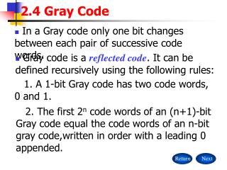
Conversion • Decimal Binary Gray Code 0 0000 0000 1 0001 0001 2 0010 0011 3 0011 0010
Project Details • Binary to Gray • Uniform cell heights of 30 μm • 7 XOR gates • 16 Mux based D-Flip Flops
Longest Path Calculations Note: All widths are in microns and capacitances in fF
Cost Analysis • We Spent Many Hours on this Project • Verifying logic = 10 hrs • Verifying timing = 30 hrs • Layout = 25 hrs • Post extracted timing = 5 hrs
Lessons Learned • START EARLY! • FOCUS in class • START EARLY!! • Utilize other students in the class • START EARLY!!! • Work as a TEAM efficiently • START EARLY!!!!
Summary • This Project explained the Fundamentals of EE-166 • Taught us the Ins - and - Outs of basic Design • Less Power Used, Less Area Used • Met Specifications
Acknowledgements • Thanks to our families for putting up with us for not being home. • Thanks to Cadence Design Systems for the VLSI lab • Thanks to Synopsys for Software donation • Dr. David Parent • Thanks to the janitors/security for letting us spend late hours in the labs.