Download
1 / 58
610 likes | 969 Views
Learn about Gray code background, binary to Gray code conversion, delegated duties, method of design, target specifications, simulation results, and more in this comprehensive guide.

E N D
8-Bit Gray Code Converter By Martin Serena, Dang Ly, Khoa Ly
Overview • Gray Code Background • Delegated Duties • Method of Design • Target Specifications • Simulation Results • Block Diagram • Schematics, Symbols, Layouts, and Simulations • Design References • Conclusion
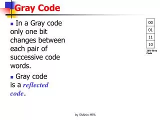
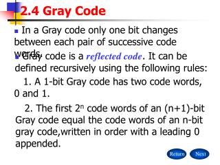
Gray Code Background • Conversion works in both directions • Binary Gray , Gray Binary • One bit changes from number to number • Not arithmetic • Not weighted (e.g. 222120) • Limits the amount of error that can occur when several bits change between numbers • No limit to number of converted bits
Binary to Gray Code Conversion 1 + 1 + 0 + 0 (BC) • MSB does not change as a result of conversion • Start with MSB of binary number and add it to neighboring binary bit to get the next Gray code bit • Repeat for subsequent Gray coded bits 1 0 1 0 (GC)
Gray to Binary Code Conversion 1 0 1 0 (GC) + + + • MSB does not change as a result of conversion • Start with MSB of binary number and add it to the second MSB of the Gray code to get the next binary bit • Repeat for subsequent binary coded bits 1 1 0 0 (BC)
Delegated Duties • Martin – Binary to Gray Conversion, Gray to Binary Conversion (XOR gates) • Dang – Binary/Gray Output Selection (MUXs) • Khoa – Binary Code Counter, Parallel-to-Parallel Shift Register (D flip-flops)
Method of Design • Decided on an initial load capacitance (Cin) • Partitioned the circuit into different propagation delay times according to gate/device requirements, and divided propagation delay times amongst the individual gates and devices • Created the symbol and layout for out each type of gate (XOR, MUX, NAND) • Connected gate symbols to create device symbols • Connected gate layouts to create device layouts • Connected device symbols to create circuit schematics, and connected device layouts to create circuit layouts
Target Specifications • Conversion: • Binary Code to Gray Code • Gray Code to Binary Code • Propagation delay times: • XOR (each): 0.4 nS • MUX (each): 0.3 nS • D flip-flop (each): 0.63 nS (worst-case fall time) • Technology specs (size): • Minimum Channel Width = 1.5 m • Minimum Channel Length = 0.6 m • Power < ¼ Watt • Clock Speed = 200 MHz • Total area as small as possible
Simulation Results • Successfully converts binary and Gray codes • Propagation Delay • XOR (each): 0.338 nS (worst-case) • MUX (each): 0.35 nS (worst-case) • D flip-flop (each): 1.14 nS (worst-case fall time) • Technology specs (size) • Transistor Lengths: 0.6 m • XOR: Wp = 3.9 m Wn = 3.75 m • MUX: Wp = 6 m Wn = 3 m • D Flip-Flop: Wp = 18 m Wn = 10 m
Simulation Results • Power (using the power meter) • 39.94 mW • Clock Speed • 200 MHz • Total Area • Gray code converter: 6.03E-4 cm2 • Counter: 10.2E-4 cm2