LSST Camera Overview
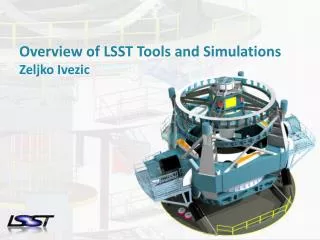
LSST Camera Overview. SLAC Program Review June 7, 2006 Kirk Gilmore Stanford/SLAC/KIPAC. Camera Assembly. Raft Tower. L3 Lens. Shutter. L1/L2 Housing. Filter in stored location. L1 Lens. Camera Housing. L2 Lens. Filter in light path. Telescope/Camera Configuration.

LSST Camera Overview
E N D
Presentation Transcript
LSST Camera Overview SLAC Program Review June 7, 2006 Kirk Gilmore Stanford/SLAC/KIPAC
Camera Assembly Raft Tower L3 Lens Shutter L1/L2 Housing Filter in stored location L1 Lens Camera Housing L2 Lens SLAC Program Review June 7, 2006 Filter in light path
Telescope/Camera Configuration SLAC Program Review June 7, 2006
Flowdown from Science to Camera Four Main Science Themes for LSST: 1. Constraining Dark Energy and Dark Matter 2. Taking an Inventory of the Solar System 3. Exploring the Transient Optical Sky 4. Mapping the Milky Way MajorImplications to the Camera: • Large Etendue • Excellent Image Quality and Control of PSF Systematics • High Quantum Efficiency over the Range 320 – 1,050 nm • Fast Readout SLAC Program Review June 7, 2006
Large Etendue
Excellent Image Quality with ~10 micron (0.2 arc-sec ) diameter images Camera: Flat 64 cm f CCD array Aspheric surface
SDSS Band-pass Transition Half Maximum Transmission Wavelength (nm) g r i z Blue side 402 552 693 840 Red side 548 693 851 - Photometric redshifts of galaxies Separation of stellar populations Photometric selection of quasars LSST Band-pass Transition Half Maximum Transmission Wavelength (nm) u g r i z Y Blue side 350 400 552 691 818 948 Red side 400 552 691 818 922 1050 G-Balmer break @400. OI line@ 557 R-matches SDSS I-red side short of sky emission @826 Z-red side stop before H2O bands Y– red side cut-off by sensor
Optics Summary • Baseline design of LSST camera optics exists • Refinements continuing • Optics fabrication discussed with vendors • Substantial industrial base exists for optics fabrication • Optics coating discussed with vendors • Adequate industrial base exists for optics coating Next steps • Complete tolerance analysis for camera optics • Complete RFQ for filter coating risk reduction study SLAC Program Review June 7, 2006
Sensor Requirements • High QE to 1000nm thick silicon (> 75 µm) • PSF << 0.7” (0.2”) high internal field in the sensor high resistivity substrate (> 5 kohm∙cm) high applied voltages (30 - 50 V) • Fast f/1.2 focal ratio sensor flatness < 5µm package with piston, tip, tilt adj. to ~1µm • Wide FOV ~ 3200 cm2 focal plane > 200-CCD mosaic (~16 cm2 each) industrialized production process required • High throughput > 90% fill factor 4-side buttable package, sub-mm gaps • Fast readout (1 - 2 s) segmented sensors (~6400 TOTALoutput ports) SLAC Program Review June 7, 2006
Detail of output port Full CCD showing segmentation. Note pads on left and right edges only Detail of one edge Multi-port 4K x 4K = 16M Pixel CCD strawman 32 segments/port J. Geary, “LSST Strawman CCD Design”, Dec. 2004
Control of PSF Monte-Carlo simulation of long-wavelength light absorption silicon sensorRight-hand figures show the simulated points where 10,000 photons are absorbed. Left-hand panels show the projections onto the charge-collection plane.
Focal Plane Metrology Requirement Sensor Module 5mm p-v flatness over entire sensor surface Raft Assembly 6.5mm p-v flatness over entire surfaces of sensors Focal Plane Assembly 10mm p-v flatness over entire surfaces of sensors SLAC Program Review June 7, 2006
Sensor Study Projects • Funding mass-production vendor for design study plus fabrication of known-good CCDs on 100u high-rho silicon. • Our first tests of thick CCDs with backside bias voltage. • Verify QE, PSF, dark current performance. _______________________________________________________________ • Funding the development of a CMOS readout 4K X 4K, 10u pixel array with 100u thick high-rho material and backside bias capability. Very promising but largely untested for precision astronomical photometry. • Pros: electronic shutter, very low power, low blooming, interface ASIC. Cons: noise floor for single reads, crosstalk between channels. SLAC Program Review June 7, 2006
Focal Plane Read-out: The Challenge • Large focal plane 201 Sensors, 3.2 Gpixels • High speed readout 2 sec goal • Low read noise, sky noise dominated > ~ 5 e rms • High crosstalk immunity ~ 80 db • Fully synchronous readout across entire focal plane • Large number of sensor pads (signals) 150/sensor ~ 30,000 pads total • High vacuum environment contamination control • Minimization of vacuum feedthroughs SLAC Program Review June 7, 2006
Focal Plane Read-out: Strategy • Utilize highly segmented sensors to allow modest read speed • 32 segments (ports) / sensor 250 kHz readout • “Raft” based electronics package 9 x 32 = 288 ports per raft • Electronic package located within Dewar to avoid ~30k Dewar penetrations • FPA electronics packaging requirement All electronics must live in “shadow” of raft footprint ~ 125 mm x 125 mm • 21 rafts 6,048 readout ports (source followers) • Data output on one optical fiber per raft 144 Mpixels/2 sec ~1.4 Gbps on fiber SLAC Program Review June 7, 2006
Raft Towers Si CCD Sensor Raft Assembly CCD Carrier Thermal Strap(s) SENSOR Flex Cable & Thermal Straps Sensor Packages FEE Cage FEE Raft Structure RAFT TOWER RAFT SLAC Program Review June 7, 2006
In-dewar electronics partitioning 32-port CCD 32-port CCD 32-port CCD RIGHT LEFT • Front End Boards (6 per raft): • 48-channel video signal chain through CDS processing • clock and bias drive • ASIC-based 180K Flex cables (~ 20,000 signals) Cold sink 240K • BEE motherboard and backplane: • differential receiver • signal chain ADC • frame buffer • data transport to optical fiber • clock pattern generation • clock and bias DACs SLAC Program Review June 7, 2006
Camera Overview Tasks and Summary • Detector requirements: (Radeka/Geary - BNL/SAO) • 10 mm pixel size Pixel full-well > 90,000 e– High QE 400 – 1000 nm • Low noise (< 5 e– rms), fast (< 2 sec) readout, stable T (-90 C) • Package large number of detectors, with integrated readout electronics, • with high fill factor and serviceable design (O’Connor/Oliver - BNL/Harvard) • Sensor and focal plane precision alignment/stabilility/motion control Sensor flatness 5u p-v, focal plane flatness 10u p-v(Takacs/Rasmussen/Schindler - BNL/SLAC/SLAC) • Fabricate large diameter (75cm) filters with uniform coatings (Olivier - LLNL) • Constrained volume (camera in beam) (Nordby - SLAC) • Makes shutter, filter exchange mechanisms challenging • Focal Plane Calibration - (Burke - SLAC) SLAC Program Review June 7, 2006