Download
1 / 41
1.92k likes | 4.05k Views
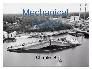
3 – Fracture of Materials . Part of the top of an Aloha Airlines jet peeled of during the flight. Liberty Ship failures involved both brittle fractures and fatigue fractures.

E N D
Part of the top of an Aloha Airlines jet peeled of during the flight
Liberty Ship failures involved both brittle fractures and fatigue fractures. Of 2700 ships built, 400 suffered hull and deck fractures. 90 were considered serious and in 20 ships fracture was essentially total with 10 ships breaking in half without warning.
Outline • Fracture of Materials Types of Fracture Brittle Fracture Ductile Fracture Brittle to Ductile Transition • Fracture Mechanics • Stress Concentration • LEFM • K & G • Kc • Appendix - Griffith Theory
Fracture • Fracture: separation of a body into pieces due to stress, attemperatures below the melting point. • Steps in fracture: • Crack formation • Crack propagation • Depending on the ability of material to undergo plastic • deformation before the fracture two fracture modes can bedefined - ductile or brittle
Ductile fracture - most metals (not too cold): • Extensive plastic deformation ahead of crack • Crack is “stable”: resists further extension unlessapplied stress is increased • Brittle fracture - ceramics, ice, cold metals: • Relatively little plastic deformation • Crack is “unstable”: propagates rapidly withoutincrease in applied stress • Ductile fracture is preferred in most applications
Brittle vs. Ductile Fracture Ductile materials- extensive plastic deformation and energy absorption (“toughness”) before fracture Brittle materials- little plastic deformation and low energy absorption before fracture
Brittle vs. Ductile Fracture • Brittle fracture; (b) Shearing fracture in single crystal • (c) Completely ductile (d) Ductile fracture
Ductile Fracture • Necking, (b) Cavity Formation, • (c) Cavity coalescence to form a crack,
Ductile Fracture (d) Crack propagation, (e) Fracture
Ductile Fracture (Cap-and-cone fracture in Al)
Ductile Fracture Scanning Electron Microscopy: Fractographic studies athigh resolution. Spherical “dimples” correspond tomicro-cavities that initiate crack formation.
Brittle Fracture • No appreciable plastic deformation • Crack propagation is very fast • Crack propagates nearly perpendicular to thedirection of the applied stress • Crack often propagates by cleavage –breakingof atomic bonds along specificcrystallographic planes (cleavage planes)
Brittle Fracture Brittle fracture in a mild steel
Brittle Fracture • Transgranular fracture: Fracture cracks pass throughgrains. Fracture surface have faceted texture becauseof different orientation of cleavage planes in grains. • Intergranular fracture: Fracture crack propagation isalong grain boundaries (grain boundaries are weakenedor embrittled by impurities segregation etc.)
Ductile-to-Brittle Transition Ductile-to-Brittle Transition: As temperature decreases a ductile material can becomebrittle • Alloying usually increases the ductile-to-brittle transitiontemperature. • FCC metals remain ductile down to very lowtemperatures. • For ceramics, this type of transition occursat much higher temperatures than for metals.
Ductile-to-Brittle Transition DBTT:Ductile-Brittle Transition Temperature
Stress Concentration Energy Release Rate Crack Tip Plasticity Fracture Toughness Fracture Mechanics & Fracture Toughness
Stress Concentration For a long crack oriented perpendicular to the appliedstress the maximum stress near the crack is: m 2 (a/)1/2 (1) where σis the applied external stress, a is the half-lengthof the crack, and ρthe radius of curvature of the crack tip.(note that a is half-length of the internal flaw, but the fulllength for a surface flaw).
Stress Concentration Factor The ratio of the maximum stress and the nominal applied tensile stress is denoted as the stressconcentration factor, Kt, where Ktcan be calculated by Equation 1. The stress concentrationfactor is a simple measure of the degree to which an external stress is amplified at the tip of asmall crack.
Stress Concentration The stress distribution at the crack tip in a thin plate for an elastic solid is given by: (2)
Stress Concentration K:Stress Intensity Factor (3) Unit of K: psiin, MN/(m3/2), or MPam
Stress Concentration Substitute K into Equation (3): (4)
Stress Concentration Opening In-plane Shear Out-of-Plane Shear Fracture Modes
Energy Release Rate Energy Release Rate: In 1956, Irwin defined an energy release rate, G, which is a measure of the energy available for an increment of crack extension: G = - dU/dA Since G is obtained from the derivative of a potential, it is also called the crack extension force or crack driving force
Energy Release Rate Griffith Approach: G = 2a/E Where is the nominal stress, a is half-length of crack, E is Young’s Modulus
Relationship between K and G Mode I Plain Stress: G = KI2/E Plain Strain: G = KI2(1-2)/E
Crack Tip Plasticity Irwin Approach
Crack Tip Plasticity Irwin Approach
Fracture Toughness Kc: If we assume a material fails locally at some combination of stresses and strains, then crack extension must occur at a critical K value. This Kc value, which is a measure of fracture toughness, is a material constant that is independent of the size and geometry of the cracked body.
Fracture Toughness Measurement • MEASURE STRENGTH WITH A CRACK OF KNOWN LENGTH • SHARP CRACK • LINEAR ELASTIC? • SMALL PROCESS ZONE RULES • ASTM STANDARDS: E-399
SUMMARY • Types of Fracture: Brittle Fracture Ductile Fracture • Ductile Fracture: Crack initiation, crack growth, fracture, fractography • Brittle Fracture: Intergranular & Transgranular (Cleavage) • Brittle to Ductile Transition: DBTT
SUMMARY – Cont’d • Stress Concentration Stress distribution in front of the crack tip Stress concentration factor • Linear Elastic Fracture Mechanics K: Stress Intensity Factor G: Energy Release Rate Relationship between K & G Crack tip plasticity • Fracture Toughness
Appendix - Griffith Theory for Brittle Fracture For defect-free material: sth ~ E/10 is orders of magnitude higher than usually observed Where E – Young’s modulus g – specific surface energy a0 – lattice parameter sth – theoretical strength of the material
Energy criterion: when rate of change of the release of elastic energy with respect to crack size rate at which energy is consumed to create new surfaces, fracture occurs Energy criterion for brittle fracture (Griffith Theory) Onset: Where s– Griffith’s stress (the critical stress) gs – surface energy/per unit area
Griffith equation is only for glasses & ceramics – brittle fracture, no plastic deformation occurs prior to fracture Metals and polymers plastic deformation occurs before fracture modified Griffith equation (Orowan equation) Griffith Equation