Download
1 / 62
670 likes | 993 Views
ME 350 – Lecture 12. NONTRADITIONAL MACHINING PROCESSES Mechanical Energy Processes (USM, WJC, AJM) Thermal Energy Processes (EDM, Wire EDM, EBM, LBM, PAC) Electrochemical Processes (ECM) Chemical Processes (CHM, Chemical Blanking, PCM)

E N D
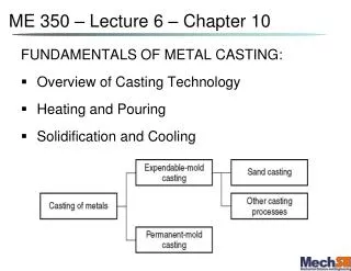
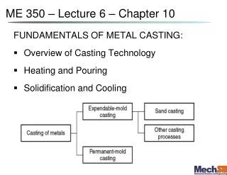
ME 350 – Lecture 12 NONTRADITIONAL MACHINING PROCESSES • Mechanical Energy Processes (USM, WJC, AJM) • Thermal Energy Processes (EDM, Wire EDM, EBM, LBM, PAC) • Electrochemical Processes (ECM) • Chemical Processes (CHM, Chemical Blanking, PCM) Nontraditional machining is characterized by material removal that:
Nontraditional Processes Used When: • Material is either very hard, brittle or both; or material is very ductile: • Part geometry is complex or geometric requirements impossible with conventional methods: • Need to avoid surface damage or contamination that often accompanies conventional machining:
1. Mechanical Energy Processes • Ultrasonic machining (USM) • Water jet cutting (WJC) • Abrasive jet machining (AJM)
1a) Ultrasonic Machining (USM & UW) Abrasives in a slurry are driven at high velocity against work by a vibrating tool (low amplitude & high frequency) • Tool oscillation is perpendicular to work surface • Abrasives accomplish material removal • Tool is fed slowly into work • Shape of tool is formed into part
USM Applications • Used only on hard and brittle work materials: ceramics, glass, carbides, and metals. • Shapes include non-round holes, holes along a curved axis • “Coining operations” - pattern on tool is imparted to a flat work surface • Produces virtually stress free shapes • Holes as small as 0.076 mm have been made
1b) Water Jet Cutting (WJC) • Uses high pressure, high velocity stream of water directed at work surface for cutting
WJC Applications • Usually automated using CNC or industrial robots • Best used to cut narrow slits in flat stock such as: plastic, textiles, composites, tile, and cardboard • Not suitable for: materials • When used on metals, you need to add to the water stream: • Smallest kerf width about 0.4 mm for metals, and 0.1mm for plastics and non-metals. • More info: http://www.waterjets.org/index.html
WJC Advantages • No crushing or burning of work surface • Minimum material loss • No environmental pollution • Ease of automation
1c) Abrasive Jet Machining (AJM) High velocity gas stream containing abrasive particles (aka: sand blasting or bead blasting) • Normally used as a finishing process rather than cutting process (e.g. gas sandpaper) • Applications: deburring, cleaning, and polishing.
2. Thermal Energy Processes - Overview • Very high temperatures, but only: locally • Material is removed by: • Problems and concerns: • Redeposition of vaporized metal • Surface damage and metallurgical damage to the new work surface • In some cases, resulting finish is so poor that subsequent processing is required
Thermal Energy Processes • Electric discharge machining (EDM) • Electric discharge wire cutting (Wire EDM) • Electron beam machining (EBM) • Laser beam machining (LBM) • Plasma arc cutting or machining (PAC)
2a) Electric Discharge Machining (EDM) • One of the most widely used nontraditional processes • Shape of finished work is inverse of tool shape • Sparks occur across a small gap between tool and work • Holes as small as 0.3mm can be made with feature sizes (radius etc.) down to ~2μm
Work Materials in EDM • Work materials must be: • Hardness and strength of work material are: • Material removal rate depends primarily on: • Applications: • Molds and dies for injection molding and forging • Machining of hard or exotic metals • Sheetmetal stamping dies.
2b) Wire EDM • EDM uses small diameter wire as electrode to cut a narrow kerf in work – similar to a: bandsaw
Material Removal Rate of EDM • Weller Equation (Empirical); Maximum rate: RMR = whereK = 664 (°C1.23∙mm3/amp∙s);I= discharge current; Tm = melt temp of work material • Actual material removal rate: MRR = vf∙h∙wkerf wherevf= feed rate;h= workpiece thickness;wkerf = kerf width While cutting, wire is continuously advanced between supply spool and take‑up spool to: maintain a constant diameter
Wire EDM Applications • Ideal for stamp and die components • Since kerf is so narrow, it is often possible to fabricate punch and die in a single cut • Other tools and parts with intricate outline shapes, such as lathe form tools, extrusion dies, and flat templates
2c) Electron Beam Machining (EBM) • Part loaded inside a vacuum chamber • Beam is focused through electromagnetic lens, reducing diameter to as small as 0.025 mm • Material is vaporized in a very localized area
EBM Applications • Ideal for micromachining • Drilling small diameter holes ‑ down to 0.05 mm (0.002 in) • Cutting slots only about 0.025 mm (0.001 in.) wide • Drilling holes with very high depth‑to‑diameter ratios • Ratios greater than 100:1 • Disadvantage: slow and expensive
2d) Laser Beam Machining (LBM) • Generally used for: drilling, slitting, slotting, scribing, and marking operations • Holes can be made down to 0.025 mm • Generally used on thin stock material
2e) Plasma Arc Cutting (PAC) • Uses plasma stream at very high temperatures to cut metal 10,000°C to 14,000°C • Plasma arc generated between electrode in torch and anode workpiece • The plasma flows through water‑cooled nozzle that constricts and directs plasma stream to desired location
Applications of PAC • Most applications of PAC involve cutting of flat metal sheets and plates • Hole piercing and cutting along a defined path • Can be operated by hand‑held torch or automated by CNC • Can cut any: • Hole sizes generally larger than 2 mm
3. Electrochemical Machining Processes • Electrical energy used in combination with chemical reactions to remove material • Reverse of: electroplating • Work material must be a: • Feature dimensions down to about 10 μm Courtesy of AEG-Elotherm-Germany
Electrochemical Machining (ECM) Material removal by anodic dissolution, using electrode (tool) in close proximity to work but separated by a rapidly flowing electrolyte
ECM Operation Material is deplated from anode workpiece (pole) and transported to a cathode tool (pole) in an electrolyte bath • Electrolyte flows rapidly between two poles to carry off deplated material, so it does not: • Electrode materials: Cu, brass, or stainless steel • Tool shape is the: • Tool size must allow for the gap
ECM Applications • Die sinking - irregular shapes and contours for forging dies, plastic molds, and other tools • Multiple hole drilling - many holes can be drilled simultaneously with ECM • No burrs created – no residual stress Schuster et al, Science 2000 Trimmer et al, APL 2003
Material Removal Rate of ECM • Based on Faraday's First Law: rate of metal dissolved is proportional to the current MRR = Aƒr = ηCI whereI = current;A = frontal area of the electrode (mm2), ƒr = feed rate (mm/s), and η = efficiency coefficient • = specific removal rate with work material; • M = atomic weight of metal (kg/mol) • ρ = density of metal (kg/m3), • F = Faraday constant (Coulomb) • n = valency of the ion;
Equations for ECM (Cont’) • Resistance of Electrode: Gap, g Area, A ρ is the resistivity of the electrolyte fluid (Ohm∙m)
In-class Exercise: ECM through a plate • Aluminum plate, thickness t = 12 mm; • Rectangular hole to be cut: L = 30mm, W = 10mm • Applied current: I = 1200 amps. • Efficiency of 95%, • MRR = Aƒr = ηCI Determine how long it will take to cut the hole? 10mm 30mm Ideal CAl = 3.44×10⁻² mm3/amp∙s - other ‘C’ values in Table 26.1
4. Chemical Machining (CHM) CHM Process: • Cleaning ‑ to insure uniform etching • Masking ‑ a maskant (resist, chemically resistant to etchant) is applied to portions of work surface not to be etched • Patterning of maskant • Etching ‑ part is immersed in etchant which chemically attacks those portions of work surface that are not masked • Demasking ‑ maskant is removed
Maskant - Photographic Resist Method • Masking materials contain photosensitive chemicals • Maskant is applied to work surface (dip coated, spin coated, or roller coated) and exposed to light through a negative image of areas to be etched • These areas are then removed using photographic developing techniques • Remaining areas are vulnerable to etching • Applications: • Small parts on thin stock produced in high quantities • Integrated circuits and printed circuit cards
Material Removal Rate in CHM • Generally indicated as penetration rates, i.e. mm/min. • Penetration rate unaffected by exposed surface area • Etching occurs downward and under the maskant • In general, d ≤ u ≤ 2d, Etch Factor: Fe= (see Table 26.2 pg 637)
Chemical Blanking • Uses CHM to cut very thin sheetmetal parts ‑ down to 0.025 mm thick and/or for intricate cutting patterns • Conventional punch and die does not work because stamping forces damage the thin sheetmetal, or tooling cost is prohibitive Parts made by chemical blanking (photo courtesy of Buckbee-Mears St. Paul).
CHM Possible Part Geometry Features • Very small holes • Holes that are not round • Narrow slots in slabs and plates • Micromachining • Shallow pockets and surface details in flat parts • Special contoured shapes for mold and die applications
Advanced Manufacturing Processes • Top-down vs Bottom-up approach • Electrospinning • Plasma Jet Forming • Hot Embossing/Imprinting • Templating • Soft Lithography • Self Assembly
Top Down technology • Making objects by molding and removing large pieces of bulk material (much like a sculptor creating a sculpture). • Accuracy and production rate affected by the sculpting tool or writing tools • State of Art: Focused Ion Beam (7nm features) NEC diamond nanocup f:2.75 micron H: 12 micron
Bottom Up Technology • Objects are constructed from assembling smaller building blocks (a thermodynamic driven process). • Building blocks: • (dots, wires, tubes, particles, fibers) mass produced from a wide range of materials with precise control of size, shape, etc. • They follow a certain rule (surface chemistry, Gibbs free energy, etc) to link with each other
A Partial List of Advanced Manufacturing technologies • Top-Down Approaches • Electrospinning • Plasma Jet Forming • Hot Embossing/Imprinting • Bottom-Up Approaches • Templating (inorganic: alumina, organic: Protein, DNA) • - Soft Lithography • - Self-assembly of Colloid crystals
Electro-spinning Y. Xia, U. Washington
Why? Fibers can be made much thinner (down to 100nm) How? Voltage applied to the droplet to reduce the surface tension, resulting in a very thin fiber. The Electrospinning Process - High Voltage (8 to 25kV) - Fiber diameter ~1/V. - Randomly arranged on the collection plate forming a mesh network.
Plasma Jet Forming Prof. Steve Girshick, Minnesota - Plasma Jet produce Si, Ti and B based hard carbide and nitride films - Use aerodynamic lenses to produce nanostructured micropatterns
Nanoimprinting /Hot Embossing E.g. mass production of CD or DVD
A Partial List of Advanced Manufacturing technologies • Top-Down Approaches • Electrospinning • Plasma Jet Forming • Hot Embossing/Imprinting • Bottom-Up Approaches • Templating (inorganic: alumina, organic: Protein, DNA) • - Soft Lithography • - Self-assembly of Colloid crystals
Inorganic Template: Anodic Alumina • Anodization of Al form self organized honeycomb microstructures • Pore diameter(10-500nm) and packing densities are functions of acid strength and voltage in anodization step Nanoporous Anodic alumina
Soft Lithography • Developed by Whitesides group at Harvard Microcontact printing – Elastomeric stamp – Patterns of self-assembled monolayers (SAMs) and proteins – SAMs allow a variety of surface modifications Thickness variation by changing tail length Modification of tail group changes surface properties Variety available for different substrate materials – Fabricated using a PDMS mold
Micro Contact Printing (μCP) The elastomer (PDMS) masks inked with adsorbing or assembling molecules, and then used as small rubber contact stamps The chemical ink covers all surfaces, but Surface relief patterns transfer only molecules in direct contact. Inks can be adsorbing polymers, reactant compounds, or self assembling monolayers
Micro Contact Printing (μCP) - Self-assembled monolayer with tailored headgroups - Provide selectivity such as polymer adsorption, vapor deposition of inorganics, and electroplating of metals… - PDMS Stamps can deposit controlled patterns with down to 10nm features J. Rogers, UIUC
Micro Contact Printing (μCP) Complex architectures are possible from any master, as long as it’s limited to a single layer to be deposited on a flat surface The Limitation: This produces only a single layer.
Micro Contact Molding Liquid pre-polymer flows into PDMS channels by capilliary action, hardens over time, and with mask removal the desired structures are left behind