Download
1 / 34
340 likes | 633 Views
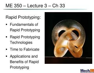
ME 350 – Lecture 3 – Ch 33 . Rapid Prototyping: Fundamentals of Rapid Prototyping Rapid Prototyping Technologies Time to Fabricate Applications and Benefits of Rapid Prototyping. The Simplified Manufacturing Process. Prototypes –

E N D
ME 350 – Lecture 3 – Ch 33 Rapid Prototyping: • Fundamentals of Rapid Prototyping • Rapid Prototyping Technologies • Time to Fabricate • Applications and Benefits of Rapid Prototyping
The Simplified Manufacturing Process Prototypes – to visualize your idea, for functional demonstration, tests, evaluation, etc. Manufacturing
Why Rapid Prototyping (RP) ? • Model from clay • Carve from wood • Bend wire meshing • Carve from Styrofoam – perhaps with surface reinforcement • Mill from a block of plastic or aluminum (3- or 4-axes machines)
Additive RP • Adds layers of material one at a time to build the solid part from the to the • Build-up of complex 3D shapes from 2D layers • Also called Layered Manufacturing (LM) or Solid Freeform Fabrication (SFF)
Classification of RP Technologies The RP classification is based on the form of the starting material: • Liquid-based: monomers are deposited in layers (SLA & FDM & Objet) • Solid-based: solid sheets that are to create the solid part (LOM) • Powder-based: powders that are (SLS & 3DP)
Ford Lab RP Machines We now have 3 high resolution RP machines in the Ford Lab (MEL): • OBJET by Eden: printing followed by UV light soak/harden at each layer (www.objet.com) • SLA by 3D Systems: Liquid cured by UV laser, layer by layer (www.3Dsystems.com) • SLS by EOS: powders that are by a laser, layer by layer (www.EOS.info)
Liquid RP: Stereolithography Apparatus (SLA) Part made out of a photosensitive liquid polymer selectively cured using a directed laser beam • Earliest RP method demonstrated • More installations than any other RP method
+ UV light radical Initiator + +heat monomer + +heat Polymer Chemistry of Photoforming Initiation: Line Pattern Illuminated Propagation: Radical diffusion Termination:
Laser Scanning Profile Scanning direction, speed U t D Volume solidification rate: Q ≈
Part Build Time in SLA Time to complete a single layer : where Ti = time to complete layer i; Ai = area of layer i; v = average scanning speed of the laser beam at the surface; D = diameter of the “spot size,” assumed circular; and Td = delay time between layers to reposition the worktable
Example Problem 1 Stage movement: 0.2mm/step, 10s/step Laser: 1m/s (velocity) 0.2mm (dia.) 10mm Number of layers? 10mm 20mm Time to “write” one layer? Total time to fabricate? Volumetric method for approximating time to fabricate?
SLA: • Layers are each 25-50 μm thick • Support “pillars” (~100 μm dia.) needed every 2-3 mm • Recent material improvements: • In the past only brittle fragile yellow photopolymer available • Now lots of material choice, we use either a strong rigid clear photopolymer or a white ductile semi-elastomeric photopolymer • Less shrinkage during UV cure (<1%) than in the past (1-2%) Pros: • Uses less support structures than some other methods • Can produce the highest resolution surface features Cons: • No easy way to remove support scaffolding → must cut • Messy to clean
2μm SLA – resolution pushed to the extreme Spiral Lattice (Zhang, Berkeley) The Nanobull (Kawata, Japan) 200μm Resolution down to 75 nanometers are feasible!
Fused Deposition Modeling (FDM) • Droplets or a continuous filament of a molten wax, thermoplastic or slurry are printed from a jet or heated needle extruder head onto a platform surface. • Extrudate is solidified and cold welded to the cooler surface very rapidly. • Need to build a complete support structure everywhere there are overhangs / bridges. • Support material is water soluble (FDM systems generally have at least two extruder heads) • Surface finish is generally not a good as SLA • Layer to layer delay is generally much less than SLA
Fused Deposition Modeling Filament extruding D Ink binder U Volume solidification rate: Profs. J.Lewis and A. Alleyne, UIUC
FDM machines and structures made Filament of support material Finished shape
10 µm 10 µm Direct Deposition of Microstructures J. Lewis, Nature, 2004
FDM: Pros and Cons Pros: • Potential for high resolution Cons: • Overhanging structures need a lot of • High resolution → small filament → • Difficult to achieve surface
Laminated Object Manufacturing (LOM) Solid physical model made by: • Sheet stock (typically plastic or paper cellulose), is advanced and heat bonded (usually by a heated roller) to previous layer • Laser outlines part, then crosshatches area to be later removed • Sheet stock advanced again, and process repeated. • Excess material removed at completion with putty knife or similar.
LOM: Pros and Cons Pros: • Minimal heating and no chemical development • Low shrinkage and low stress • Minimal tooling path around outlines • No supports needed • Cheap and non-toxic materials Cons: • Delicate parts can be damaged when removing tiles (i.e. “crosshatched” regions). • Wasted materials • Rough surface and limited finishing process • Burning fumes
Powder-based Approaches Key Properties: • Needs that must be removed! Uniform bed of powder acts as support. • Powder gets selectively (locally) glued (or fused) together to create the solid portions of the desired part.
1) Selective Laser Sintering (SLS) Moving laser beam sinters heat‑fusible powders in areas corresponding to the CAD geometry model one layer at a time to build the solid part • After each layer is completed, a new layer of loose powders is spread across the surface • Layer by layer, the powders are gradually bonded by the laser beam into a solid mass that forms the 3-D part geometry • In areas not sintered, the powders are loose and can be poured out of completed part
2) Three Dimensional Printing (3DP) - Powder Part is built layer-by-layer using an ink-jet printer to eject adhesive bonding material onto successive layers of powders • Binder is deposited in areas corresponding to the cross sections of part, as determined by slicing the CAD geometric model into layers • The binder holds the powders together to form the solid part, while the unbonded powders remain loose to be removed later • To further strengthen the part, a sintering step can be applied to bond the individual powders
Three Dimensional Printing – Powder Based Three dimensional printing: (1) powder layer is deposited, (2) ink-jet printing of areas that will become the part, and (3) piston is lowered for next layer (key: v = motion).
3D Printing: The Z402 3D Printer • Speed: 1-2 vertical inches per hour • Build Volume: 8" x 10" x 8" • Layer thickness: 3 to 10 mils, selectable
3D Printing: Pros and Cons Pros: • Color ! • Running expenses: moderate,(but overpriced powder) Cons: • Color print head and tubes need some care in maintenance. • Lot’s of dust everywhere • Slow
RP Applications • – to visualize your idea, for wind tunnel testing, or for small batches • for casting mold • testing • To make parts with geometries • - one-of-a-kind parts
Problems with Rapid Prototyping • Staircase appearance for a sloping part surface due to layering • Shrinkage and distortion of RP parts • Limited variety of in RP • Mechanical performance of the fabricated parts is limited by the materials that must be used in the RP process • Removal of where applicable