Download
1 / 35
360 likes | 579 Views
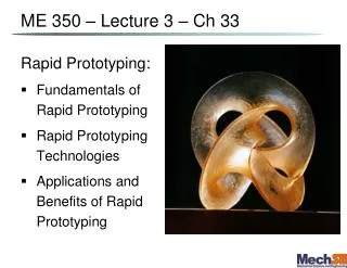
ME 350 – Lecture 3 – Ch 33 . Rapid Prototyping: Fundamentals of Rapid Prototyping Rapid Prototyping Technologies Applications and Benefits of Rapid Prototyping. Rapid Prototyping (RP) .

E N D
ME 350 – Lecture 3 – Ch 33 Rapid Prototyping: • Fundamentals of Rapid Prototyping • Rapid Prototyping Technologies • Applications and Benefits of Rapid Prototyping
Rapid Prototyping (RP) A family of fabrication processes developed to make engineering prototypes in minimum lead time based on a CAD model of the item • Traditional methods for net-shape parts involves making molds or dies. • Lead time is typically weeks or months, depending on part complexity and difficulty • RP allows a part to be made in hours or days
Additive RP • Adds layers of material one at a time to build the solid part from the bottom to the top • Build-up of complex 3D shapes from 2D layers • Also called Layered Manufacturing (LM) or Solid Freeform Fabrication (SFF)
Classification of RP Technologies The RP classification is based on the form of the starting material: • Liquid-based: monomers are photopolymers or thermoplastics deposited in layers (SLA & FDM & Objet) • Solid-based: solid sheets that are laminated to create the solid part (LOM) • Powder-based: powders that are bonded(thermally or by selective dispensing of a binder) (SLS & 3DP)
Ford Lab RP Machines We now have 3 high resolution RP machines in the Ford Lab (MEL): • OBJET by Eden: photopolymer ink jet printing followed by UV light soak/harden at each layer (www.objet.com) • SLA by 3D Systems: Liquid photopolymer in a bath cured by UV laser, layer by layer (www.3Dsystems.com) • SLS by EOS: powders that are bondedthermally by a laser, layer by layer (www.EOS.info)
Liquid RP: Stereolithography (SLA) Part made out of a photosensitive liquid polymer selectively cured using a directed laser beam • Earliest RP method demonstrated • More installations than any other RP method
Laser Scanning Profile Scanning direction, speed U t D Volume solidification rate: Q ≈ D∙t ∙U
Part Build Time in SLA Time to complete a single layer : where Ti = time to complete layer i; Ai = area of layer i; v = average scanning speed of the laser beam at the surface; D = diameter of the “spot size,” assumed circular; and Td = delay time between layers to reposition the worktable
SLA: • Layers are each 25-50 μm thick • Support “pillars” (~100 μm dia.) needed every 2-3 mm • Recent material improvements: • In the past only brittle fragile yellow photopolymer available • Now lots of material choice, we use either a strong rigid clear photopolymer or a white ductile semi-elastomeric photopolymer • Less shrinkage during UV cure (<1%) than in the past (1-2%) Pros: • Uses less support structures than some other methods • Can produce the highest resolution surface features Cons: • No easy way to remove support scaffolding → must cut • Messy to clean
2mm Precision microfabrication by SLA Spiral Lattice (Zhang, Berkeley) The Nanobull (Kawata, Japan) 200mm Resolution down to 75 nanometers are feasible!
Fused Deposition Modeling (FDM) • Droplets or a continuous filament of a molten wax, thermoplastic or slurry are printed from a jet or heated needle extruder head onto a platform surface. • Extrudate is solidified and cold welded to the cooler surface very rapidly. • Need to build a complete support structure everywhere there are overhangs / bridges. • Support material is water soluble (FDM systems generally have at least two extruder heads) • Surface finish is generally not a good as SLA • Layer to layer delay is generally much less than SLA
Fused Deposition Modeling Filament extruding D Ink binder U Volume solidification rate: Profs. J.Lewis and A. Alleyne, UIUC
FDM machines and structures made Filament of support material Finished shape
10 µm 10 µm Direct Deposition of Microstructures J. Lewis, Nature, 2004
FDM: Pros and Cons Pros: • Potential for high resolution • Inexpensive Cons: • Overhanging structures need a lot of support structures • High resolution → small filament → very slow • Difficult to achieve “flat” surface
Laminated Object Manufacturing (LOM) Solid physical model made by: • Sheet stock (typically plastic or paper cellulose), is advanced and heat bonded (usually by a heated roller) to previous layer • Laser outlines part, then crosshatches area to be later removed • Sheet stock advanced again, and process repeated. • Excess material removed at completion with putty knife or similar.
LOM: Pros and Cons Pros: • Minimal heating and no chemical development • Low shrinkage and low stress • Minimal tooling path around outlines • No supports needed • Cheap and non-toxic materials Cons: • Delicate parts can be damaged when removing tiles (i.e. “crosshatched” regions). • Wasted materials • Rough surface and limited finishing process • Burning fumes
RP: Powder-based Approaches Key Properties: • Needs no supports that must be removed! • Uniform bed of powder acts as support. • This powder gets selectively (locally) glued (or fused) together to create the solid portions of the desired part.
1) Selective Laser Sintering (SLS) Moving laser beam sinters heat‑fusible powders in areas corresponding to the CAD geometry model one layer at a time to build the solid part • After each layer is completed, a new layer of loose powders is spread across the surface • Layer by layer, the powders are gradually bonded by the laser beam into a solid mass that forms the 3-D part geometry • In areas not sintered, the powders are loose and can be poured out of completed part
2) Three Dimensional Printing (3DP) - Powder Part is built layer-by-layer using an ink-jet printer to eject adhesive bonding material onto successive layers of powders • Binder is deposited in areas corresponding to the cross sections of part, as determined by slicing the CAD geometric model into layers • The binder holds the powders together to form the solid part, while the unbonded powders remain loose to be removed later • To further strengthen the part, a sintering step can be applied to bond the individual powders
Three Dimensional Printing – Powder Based Three dimensional printing: (1) powder layer is deposited, (2) ink-jet printing of areas that will become the part, and (3) piston is lowered for next layer (key: v = motion).
3D Printing: The Z402 3D Printer • Speed: 1-2 vertical inches per hour • Build Volume: 8" x 10" x 8" • Layer thickness: 3 to 10 mils, selectable
3D Printing: Pros and Cons Pros: • Color ! • Running expenses: moderate,(but overpriced powder) Cons: • Color print head and tubes need some care in maintenance. • Lot’s of dust everywhere • Slow
STL Format: B-rep, solid object • An STL file is saved with the extension “.stl," case-insensitive. • STL is a triangular facet based representation that approximates surface and solid entities only. Entities such as points, lines, curves, and attributes such as layer and color will be ignored during the output process • An STL file consists of a list of facet data. • Each facet is uniquely identified by a unit normal (a line perpendicular to the triangle and with a length of 1.0) and by three vertices (corners). • The normal and each vertex are specified by three coordinates each, so there is a total of 12 numbers stored for each facet.
BLOCK facet normal 0.000000e+00 -1.000000e+00 0.000000e+00 outer loop vertex 0.000000e+00 0.000000e+00 -1.000000e+00 vertex 1.000000e+00 0.000000e+00 0.000000e+00 vertex 0.000000e+00 0.000000e+00 0.000000e+00 endloop endfacet facet normal 0.000000e+00 0.000000e+00 1.000000e+00 outer loop vertex 1.000000e+00 1.000000e+00 0.000000e+00 vertex 0.000000e+00 0.000000e+00 0.000000e+00 vertex 1.000000e+00 0.000000e+00 0.000000e+00 endloop endfacet facet normal -1.000000e+00 0.000000e+00 0.000000e+00 outer loop vertex 0.000000e+00 1.000000e+00 0.000000e+00 vertex 0.000000e+00 0.000000e+00 -1.000000e+00 vertex 0.000000e+00 0.000000e+00 0.000000e+00 endloop endfacet facet normal 0.000000e+00 0.000000e+00 1.000000e+00 outer loop vertex 1.000000e+00 1.000000e+00 0.000000e+00 vertex 0.000000e+00 1.000000e+00 0.000000e+00 vertex 0.000000e+00 0.000000e+00 0.000000e+00 endloop endfacet facet normal 0.000000e+00 -1.000000e+00 0.000000e+00 outer loop vertex 0.000000e+00 0.000000e+00 -1.000000e+00 vertex 1.000000e+00 0.000000e+00 -1.000000e+00 vertex 1.000000e+00 0.000000e+00 0.000000e+00 endloop endfacet facet normal 1.000000e+00 0.000000e+00 0.000000e+00 outer loop vertex 1.000000e+00 1.000000e+00 -1.000000e+00 vertex 1.000000e+00 0.000000e+00 0.000000e+00 vertex 1.000000e+00 0.000000e+00 -1.000000e+00 endloop endfacet facet normal 1.000000e+00 0.000000e+00 0.000000e+00 outer loop vertex 1.000000e+00 1.000000e+00 0.000000e+00 vertex 1.000000e+00 0.000000e+00 0.000000e+00 vertex 1.000000e+00 1.000000e+00 -1.000000e+00 endloop endfacet facet normal 0.000000e+00 0.000000e+00 -1.000000e+00 outer loop vertex 0.000000e+00 1.000000e+00 -1.000000e+00 vertex 1.000000e+00 0.000000e+00 -1.000000e+00 vertex 0.000000e+00 0.000000e+00 -1.000000e+00 endloop endfacet facet normal 0.000000e+00 0.000000e+00 -1.000000e+00 outer loop vertex 1.000000e+00 1.000000e+00 -1.000000e+00 vertex 1.000000e+00 0.000000e+00 -1.000000e+00 vertex 0.000000e+00 1.000000e+00 -1.000000e+00 endloop endfacet facet normal -1.000000e+00 0.000000e+00 0.000000e+00 outer loop vertex 0.000000e+00 1.000000e+00 -1.000000e+00 vertex 0.000000e+00 0.000000e+00 -1.000000e+00 vertex 0.000000e+00 1.000000e+00 0.000000e+00 endloop endfacet facet normal 0.000000e+00 1.000000e+00 0.000000e+00 outer loop vertex 1.000000e+00 1.000000e+00 -1.000000e+00 vertex 0.000000e+00 1.000000e+00 -1.000000e+00 vertex 0.000000e+00 1.000000e+00 0.000000e+00 endloop endfacet facet normal 0.000000e+00 1.000000e+00 0.000000e+00 outer loop vertex 1.000000e+00 1.000000e+00 0.000000e+00 vertex 1.000000e+00 1.000000e+00 -1.000000e+00 vertex 0.000000e+00 1.000000e+00 0.000000e+00 endloop endfacet endsolid BLOCK An Example STL File – Block.stl
The density of triangle facets change according to the geometry And it Changes with Chord Height affecting final surface resolution
STL Format: B-rep, solid object • There are two storage formats available for STL files, which are Ascii and Binary. ASCII file is human-readable but larger than binary • Each facet is part of the boundary between the interior and the exterior of the object. The orientation of the facets (which way is "out" and which way is "in") is specified redundantly • First, the direction of the normal is outward. Second, which is most commonly used now-a-day, list the facet vertexes in counter- clockwise order when looking at the object from the outside (right-hand rule).
RP Motivation • Prototypes – to visualize your idea, for wind tunnel testing, or for small batches • Patternfor casting mold • Assembly testing • To make parts with intricate internal geometries • Medical Apps - one-of-a-kind parts
Problems with Rapid Prototyping • Part accuracy or surface smoothness • Staircase appearance for a sloping part surface due to layering • Shrinkage and distortion of RP parts • Limited variety of materials in RP • Mechanical performance of the fabricated parts is limited by the materials that must be used in the RP process • Removal of support material where applicable