Precision Electro-Mechanical Periscope Mechanisms Overview
160 likes | 188 Views
Explore the intricate design and functionality of various electro-mechanical components in a periscope system, including shutters, mirrors, actuators, and controls. Detailed specifications and operational features are outlined to meet stringent on-orbit requirements.

Precision Electro-Mechanical Periscope Mechanisms Overview
E N D
Presentation Transcript
MAXIM Periscope Module Electro-Mechanical Jason Budinoff 25 April 2003
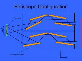
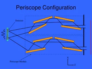
Mechanisms Overview Shutter Mirror 4 Mirror 3 Mirror 2 Mirror 1 Roll/Pitch/X translation mount OPL control translation of daughter bench w/ mirrors 2 & 3
Aperture Shutter 1 • Requirements • Command to completely obscure periscope FOV ~300 cycles over 5 years on-orbit • Duty cycle very low (close/open cycle once per observation) • Desired Operational Features • Rotate a thin (2mm) aluminum strip shutter into the periscope FOV upstream of the Thermal Pre-Collimator • Power-off hold in either open or closed position • 90 degree stoke • No launch lock required • Actuator • 90 deg stroke latching solenoid • May fail open and closed • Low risk • Flight heritage • Power TBD estimate 3 Watt • Sensor • Reed switch or LED flags • End position indication • Open, Closed
Aperture Shutter 2 Aluminum Shutter Blade Thermal Pre-Collimator Position Sensors Latching Solenoid Actuator
Differential Screw Drive Actuator 1 • Micrometer-based actuator used for mirror nano-pointing and nano-translation • Power-off hold • Low Speed • No backlash • No launch lock required • +/- 5mm (or more) stroke • 1.5* nm resolution • Closed-loop position servo removes mechanical non-linearity at the nm level • *5 nm knowledge (limited by sensor) • Coarse Adjustment Screw Provide long stroke • Use of coarse adjustment greatly increases lifetime of actuator • DC-Brushless motor drive • Fine Adjustment Differential Screw provides nm-level adjustment • “100 steps forward & 99 steps back” • 1/P1-1/P2 = 1/Peffective • DC-Brushless motor drive, 1-4 Watts @ 28V • Lubrication • Adequate for 5 years on-orbit • Bray 601 grease • Lubricant creep prevention • Nye-bar barrier film channels • Circuitous path
Differential Screw Drive Actuator 2 Bellows Provides preload and torsional rigidity for output shaft Fine adjustment stator(coils) Coarse adjustment stator(coils) Fine adjustment rotor Fine adjustment nut Coarse adj rotor T2,80 TPI LH T1, 72 TPI 32 TPI Coarse Output Shaft (rotates & translates) Housing (fixed to ground)
Optical Path Length (OPL) Control 1 • Requirements • Command a change in periscope OPL for 5 years on-orbit • Duty cycle very low (once per observation) • 1 micron resolution • +/- 1.5 mm range • Desired Operational Features • Linear Translation of mirrors 2 and 3 in X direction (perpendicular to periscope boresight) • No change in pointing during motion • No change in delta-h value during motion • Power-off hold • No launch lock • Flexure-based • Actuator • Single Coarse/Fine Differential Screw Drive • Sensor • Single 20 um pitch glass scale encoder resolution to <0.2 um • BEI or Micro-E
Optical Path Length (OPL) Control 2 • Overall Assembly Mirror 2 “Daughter” Bench Mirror 3 Optical Bench Linear Encoder between benches for OPL displacement measurement Front View OPL Actuator 2 Linear Encoders for “h” measurement Mirror 2 Mount Mirror 3 Mount Parallel Blade Flexures Back View
3-DOF Mirror Mount Mechanisms 1 • Mirror #4 Articulation Requirements • Command following adjustments to mirror 4 for 5 years on-orbit: • Linear Translation in X direction • “h” adjustment • +/- 2 mm stroke • 1.7 nm resolution • Rotation about mirror Y axis (Pitch) • +/- 5 arc sec stroke • 0.0023 arc sec (2.3 milli-arc sec) resolution • Rotation about mirror Z axis (Roll) • +/- 300 arc sec stroke • 0.13 arc sec resolution • Duty cycle very low (once per observation) • Desired Operational Features • Decoupled motion • Pitch and Roll about optical surface geometric center null point • No change in translation during Pitch or Roll adjustment • No change in pointing during translation • Power-off hold • No launch lock • Flexure-based
3-DOF Mirror Mount Mechanisms 2 Mirror 4 • Overall Assembly Mirror Mount Invar buttons bonded to bosses on rear mirror surface 3 Ti tangent -blade flexures Pitch 4-Bar Linkage Flexure Bracket Roll 4-Bar Linkage Flexure Pitch Actuator Roll Actuator X-Translation Parallel Blade Flexures X-Translation Actuator
3-DOF Mirror Mount Mechanisms 3 • X-Translation • Monolithic Parallel-Blade flexure • “parallelogram flexure” • Provides pure linear motion, weak coupling translation in pitch axis (Y) • Periscope insensitive in this axis • Simplified assembly & alignment • Uses Differential Screw Drive Actuator • Sensor is Glass scale linear encoder used for “h” measurement
3-DOF Mirror Mount Mechanisms 4 • Z-Roll Rotation Mirror “null” rotation axis at center of optical surface, at intersection of lines of action of blade flexures Differential Screw Drive Actuator Monolithic 4-Bar Linkage Flexure, non-symmetric Kaman KD 5100 inductive sensor quad
Roll Photons Mirror 4 Rolls through +/- 5 degrees to demonstrate (Exaggerated) beam path effects
3-DOF Mirror Mount Mechanisms 5 • Y-Pitch Rotation Mirror “null” rotation axis at center of optical surface, at intersection of lines of action of blade flexures Monolithic 4-Bar Linkage Flexure, non-symmetric Differential Screw Drive Actuator Kaman KD 5100 inductive sensor quad
Pitch Photons Mirror 4 Pitches through +/- 5 degrees to demonstrate (Exaggerated) beam path effects
Future Efforts • Opto-mechanical analysis of mirror mounts • Holding figure at 1/400 wave (mounted) will be *difficult* • Design & Test of Differential Screw Actuator and 5 nm position servo • IR&D funds? • Increase TRL from 3 to 5 • Further develop redundancy requirements • Actuators • Dual windings? • Failure modes? • Sensor • Redundant pairs? • Drive Electronics • A-side, B-side? • Cross strapping? • Single motor driver for all similar actuators? • Determination of failure mode for shutter • Potential redesign? • Mount on Spring-loaded release bracket? • High-Output Paraffin (HOP) actuator