MAXIM Periscope Module
MAXIM Periscope Module. Mechanical Systems Joe Pellicciotti Mick Correia Dave Palace 25 April 2003. Mechanical Design Requirements. Mass Efficiency 2 periscope assemblies (2 input apertures) on a single bench Trade study on bench materials Trade 2 bench assemblies in a single enclosure

MAXIM Periscope Module
E N D
Presentation Transcript
MAXIM Periscope Module Mechanical Systems Joe Pellicciotti Mick Correia Dave Palace 25 April 2003
Mechanical Design Requirements • Mass Efficiency • 2 periscope assemblies (2 input apertures) on a single bench • Trade study on bench materials • Trade 2 bench assemblies in a single enclosure • Thermal design will provide Delta-T stability of the periscope to be better than 0.020K • Select materials and design configuration that will meet alignment stability requirements at this temperature stability • Stability required for ~3 hour observations • Mechanical Stability Requirements:
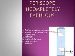
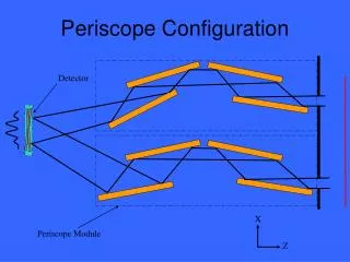
Periscope Assembly Assy. Kinematic Mounts (3) Shutter Mechanism (one for each aperture) Entrance Aperture (Thermal Collimator)
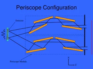
Optical Bench & Mirrors Translate Translate Entrance Aperture Mirror #1 Mirror #2 Pitch Mirror #3 Exit Aperture Mirror #4 Roll 1 DOF Mechanism Main Optical Bench Mirrors (300mm x 200mm x 50mm) 3 DOF Mechanism
Optical Bench Details Main Optical Bench Secondary Bench Translation Mechanism Secondary Bench Flexures (4/Bench) Secondary Optical Bench (Mirrors 2 & 3)
Launch Configuration Layout Delta IV ø5m x L14.3m 24 Free Flyer Satellites (4 Apertures ea.) 1 Hub Satellite (12 Apertures) 1 Detector Satellite Ø4.75m
Optical Bench Material Options † Thermal Stability based on bulk temperature change ‡ Cost & Mfg Risk rated from 1 to 5 with 5 being the highest
Summary, Recommendations & Future Work • Thermal stability requirement on the optical bench may be reduced if observation times are short (hours vs. days) • Composite bench may require additional mechanisms or stroke to compensate for moisture evaporation distortions • Baseline bench configuration has room for additional mass optimization Future Work: • Determine the allowable gradient through the optical bench that will meet distortion requirements. • Perform detailed trade study on optical bench materials • Thermal / Structural analysis • Launch Dynamics analysis • Investigate GFRP bench as next best candidate • Include methods to limit moisture absorbtion • Possibly combine 2 main benches into a single enclosure (4 entrance apertures) to reduce overall mass and volume
Back-up Information • Flexure system option for secondary Mount
Secondary Bench TranslationalPositioning System Kinematics • System Provides smooth linear motion • Negligible cross-axis motion Reference & Acknowledgement: Nicholas G. Dagalakis, John A. Kramar, Edward Amatucci, and Robert Bunch, “Kinematic Modeling and Analysis of a Planar Micro-Positioner,” National Institute of Standards and Technology, Gaithersburg, Maryland 20899