MAXIM Periscope ISAL Study Highlights
150 likes | 296 Views
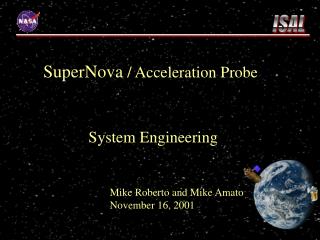
MAXIM Periscope ISAL Study Highlights. ISAL Study beginning 14 April 2003. Science Team. Webster Cash - University of Colorado 303-492-4056 Ann Shipley - University of Colorado 303-492-1875 Keith Gendreau - NASA/GSFC Code 662 6-6188. MAXIM Pathfinder.

MAXIM Periscope ISAL Study Highlights
E N D
Presentation Transcript
MAXIM Periscope ISAL Study Highlights ISAL Study beginning 14 April 2003
Science Team • Webster Cash - University of Colorado • 303-492-4056 • Ann Shipley - University of Colorado • 303-492-1875 • Keith Gendreau - NASA/GSFC Code 662 • 6-6188
MAXIM Pathfinder • “Easy” Formation Flying (mm control) • Optics in 1 s/c act like a thin lens How to implement the simple X-ray Interferometer Improved Mirror Grouping Pre FY02 Baseline Mirror Grouping Group and package Primary and Secondary Mirrors as “Periscope” Pairs • “Easy” Formation Flying (microns) • All s/c act like thin lenses- Higher Robustness • Possibility to introduce phase control within one space craft- an x-ray delay line- More Flexibility • Offers more optimal UV-Plane coverage- Less dependence on Detector Energy Resolution • Each Module, self contained- Lower Risk. Full MAXIM- the black hole imager • Nanometer formation flying • Primaries must point to milliarcseconds A scalable MAXIM concept.
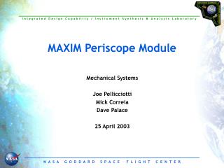
The Periscope Module- the subject of this ISAL study • The Periscope module is a convenient place to break out two radically different tolerance levels • Nm and ~mas relative positioning and pointing within the modules • Micron and arcsecond module to module alignment • Some further study makes our Periscope mirror “pairs” into mirror “quads” • 4 bounce optical situation required to maintain coarse module to module alignment
Goals for this Study • How do you make these light weight mirrors so they are flat to better than /300? • How do you hold these mirrors with actuators to move them by ~nm over microns of range? Which Actuators and controlling electronics? Do you put actuators on all the mirrors? • How does the structure provide an environment suitable to maintain the mirror figure and stability? • Do we need internal metrology? How to implement? • How do we register one module’s mirror surfaces to another modules mirror surfaces at the micron level? • How to mass produce these? By how much does this save costs? • What would the alignment procedures be? • Trade Studies- three different mirror module sizes,.. • We need the usual IMDC cost/mass/power inputs. Drawings.
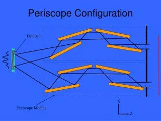
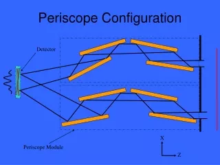
X Z A Pair of MAXIM Periscopes 2 3 Detector 1 4 Periscope Module
2 3 = 1 h2 h1 1 4 h and OPD – Key Requirements OPD < lx-ray/10
Periscope Assembly Assy. Kinematic Mounts (3) Shutter Mechanism (one for each aperture) Entrance Aperture (Thermal Collimator)
Optical Bench & Mirrors Translate Translate Entrance Aperture Mirror #1 Mirror #2 Pitch Mirror #3 Exit Aperture Mirror #4 Roll 1 DOF Mechanism Main Optical Bench Mirrors (300mm x 200mm x 50mm) 3 DOF Mechanism
Launch Configuration Layout Delta IV ø5m x L14.3m 24 Free Flyer Satellites (4 Apertures ea.) 1 Hub Satellite (12 Apertures) 1 Detector Satellite Ø4.75m ~1000 cm2 of Collecting Area
Total Costs for Optical Assemblies: ~< $60M This includes savings from mass production, prototyping, flight spares, and contingency. 1000 cm2 of effective area- full MAXIM. Still need satellite infrastructure.
The Collecting Area of Chandra for 1/10 The Cost • Chandra has 0.5 arc sec resolution and its mirrors cost $400M • This study has shown that it is possible to build a microarcsec imaging telescope with the same collecting area as the current Chandra for 1/10 its cost • The study has also shown how the engineering can be done to allow X-ray imaging and spectroscopy in formation flying
PRICE Cost Summary1st “Periscope-Pair” Cost Element (Summary Report Available for each cost element) Engineering Year Dollars ($03) Project Management Production Manufacturing Development Total Cost Estimate $23.9M Schedule Mass
Total Cost (incremental cost for T2 is $2.24M) PRICE Cost Estimate Summary Incremental Cost of 2nd Unit (T2) T1 T1 + T2