MAXIM Periscope Module
MAXIM Periscope Module. Electrical Design Estimates C. Paul Earle 25 April 2003. Design Assumptions. Design Notes & Assumptions Unregulated + 28V Supply from the S/C 1 pps timing signal + S/C time from the S/C MIL-STD-1553 Command & Data Handling Interface Requirements

MAXIM Periscope Module
E N D
Presentation Transcript
MAXIM Periscope Module Electrical Design Estimates C. Paul Earle 25 April 2003
Design Assumptions • Design Notes & Assumptions • Unregulated + 28V Supply from the S/C • 1 pps timing signal + S/C time from the S/C • MIL-STD-1553 Command & Data Handling Interface • Requirements • Provide regulated power to Sensors, Actuators, & Circuit Boards • Time-Tag Sensor Data (ie. tip/tilt/piston) based on 1pps signal from S/C • Implement Thermal Control & Monitoring • Collect Housekeeping Data – Temperatures, Voltages, Currents
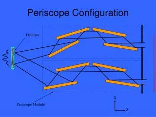
Functional Block Diagram Instrument Spacecraft Periscope (1 of 4) Instrument Electronics 1pps (1Hz) Aperture Motor (1) Actuators (4) InstrumentCPU Mechanism Drive & Control S/C C&DH 1553 I/F Sensors: Encoders (3) Tip/tilt (2) RAM H/K & Thermal Control DC/DC Converter Heaters & Temp Sensors +28V Supply +28V Survival Power Figure 1.
Instrument Architecture Address & Data Bus 1pps CPU Board (+RAM) Mech Drive Board Actuators 1553 I/F BUS H/K & Therm Board Position Sensors Sensor Board Regulated Power Power Board +28V (Unregulated) Figure 2.
Sensor Readout Board 8:1 MUX (Analog) Pre-Amps (8) Tip/Tilt Sensors (8) A/D (1) 8 Buffer (FIFO) 13:1 MUX (digital) To RAM 12:1 MUX (digital) Linear Encoders (12) 12 A/D, MUXs, FIFO Control Readout Control FPGA To/From CPU (1 Sensor Readout Board per Free Flyer) Figure 3.
Power Board Load Calculations: CPU Board = 6 Watts H/K & Thermal Board = 4 Watts Sensor Board = 4 Watts Mech Drive Board = 4 Watts Aperture Motors = 1 Watts each (no simultaneous operation) Actuators = 1 Watts each (no simultaneous operation) Total Conditioned Power = 20 Watts Assume Converter Efficiency of ~ 70% => Power Board Dissipation = (20/0.7) – 20 = 8.6 Watts
Main Electronics Box Summary Main Electronics Box Mech Drive Board (4W) Sensor Board (4W) H/K & Thermal (4W) Power Board (8.6W) 6 in (15 cm) CPU Board (6W) 6 in (15 cm) 7 in (17.5 cm) 8 in (20 cm) 10 in (25 cm) Total: ~ 26.6 Watts (avg.) Estimated Mass ~ 7 Kg Estimated Power ~ 26.6 Watts (Avg.) Estimated Size ~ (25 x 15 x 17.5) cm. Figure 4.
Instrument Power Summary Spacecraft Power Bus Requirement
Cost Estimate • Main Electronics Box ~ $4.3M • (Includes Design, Parts, Fabrication, Test, & ETU)
Conclusion • Low risk design. Essentially design re-use for each of the • circuit boards. No science data on the Free-Flyers and the • Hub spacecraft. All Sensor Data and Housekeeping Data • is passed to the spacecraft via the 1553 bus. • Design could possibly be further optimized by moving • CPU functions to the spacecraft side of the bus and • utilize the FPGA for the instrument control functions. • Packaging could possibly be reduced by combining the • actuator drive board with the sensor readout board at the • expense of drive circuitry redundancy. • Example: A single drive circuit (with one backup) could • be multiplexed to each of the actuators given non- • simultaneous operation.
Backup Slides (Electrical Design Estimates)
Processor Board Startup ROM 1553 I/F CPU (RAD 6000) 1553 I/F RAM EEPROM Memory (Thermal control logic) S/W Dev. Time Stamp Function S/C 1pps Ethernet I/F Figure 5.
- - + + Driver Amp I+ Mechanism Drive Circuit Aperture door Drive Cmd From Processor motor HK Mux Open/close detection Actuator Current + To H/K Board Actuator Voltage - Figure 6.
- - + + + + - - - - + + I+ I+ Thermal Control circuit DAC From Processor V+ Heater Tsensor HK Mux Heater Current From Processor Heater Voltage + To Central HK - Tsensor Voltage Tsensor Current VRef ISource (1 of n circuits shown) Figure 7.
HouseKeeping Circuits Mux 16-ch AD506 A/D Conv. AD 1672 H/K FIFO Power Temp ... To Controller Board . . . Mux V- Tsensor Voltage - + V+ Tsensor Current - + Mux I+ VRef ISource (1 of n temp sensors) Figure 8.