MAXIM Periscope Module: Engineering Instrument Systems for Spacecraft
140 likes | 189 Views
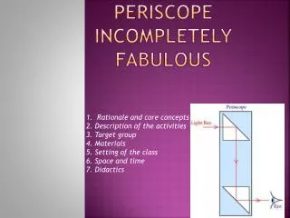
This presentation delves into the technical aspects of designing and implementing MAXIM Periscopes for space exploration. It covers key requirements, trade studies, position tolerances, and future study considerations.

MAXIM Periscope Module: Engineering Instrument Systems for Spacecraft
E N D
Presentation Transcript
MAXIM Periscope Module Instrument Systems Engineering Deborah Amato 25 April 2003
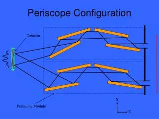
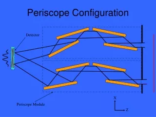
X Z A Pair of MAXIM Periscopes 2 3 Detector 1 4 Periscope Module
Launch Configuration • 1 Detector spacecraft • 26 Periscope spacecraft for 1000 cm2 of collecting area: • 25 free-flyers with 4 periscopes each • 1 hub with 12 periscopes Hub and Detector spacecraft stacked Free-flyer Launch fairing envelope
X Yaw Roll Pitch Z=LOS Y Periscope Coordinate System
MAXIM Periscope Requirements • Low mass and power • Mounted mirror surface quality = rms for = 1 • Difference in entrance and exit mirror-pair spacing, h • Optical Path Difference between periscopes, OPD < lx-ray/10 = 1Å • Relative Strehl ratio > 80% • Position Tolerances – next slide • Must be able to open and close periscope aperture • Must be able to align images on the detector plane • MAXIM Mission Periscope Parameters for this study • Periscope spacecraft swarm diameter, D = 1 km* • Focal length, F = 20,000 km* • Mirror length, m = 30 cm • Mirror width = 20 cm • Graze angle, = 1 • Wavelength, = 10Å * different values used in optical analysis
MAXIM Position Tolerancesl=1nm, F=20,000km, D=1km, m=30cm, =1deg, h=1mm
2 3 = 1 h2 h1 1 4 h and OPD – Key Requirements OPD < lx-ray/10
Trade Studies • Mirror width: 2 cm, 10 cm, 20 cm, 30 cm • Need to quantify the flux requirement for initial calibration • Baseline design: 20 cm wide mirrors • Trade mirror size versus number of spacecraft – discussed in Optical Analysis section • Consider 20 cm versus 30 cm wide mirrors in future studies • Mounted mirror surface quality is dependent on graze angle: rms for = 1 rms for = 2 • Chose = 1 for this baseline design • Internal metrology • Baseline design uses absolute position encoders calibrated with lasers in ground testing.
Periscope Power Summary Spacecraft Power Bus Requirement
Future Studies • This study looked at internal periscope issues – periscope to periscope tolerancing issues still need to be addressed. • Look at operational control and/or mechanical options • Mirror width • 2 cm width feasible? • 30 cm width versus fewer spacecraft • Mirror material is a factor in this trade (silicon vs. ULE) • Further thermal and mechanical design optimization should be done. • See other subsystem presentations for other potential issues.
Up Next • Dennis Evans will discuss the optical analysis next.