Download
1 / 74
740 likes | 784 Views
MAXIM Periscope Module. Optics Dennis Charles Evans 25 April 2003. 30 cm. Mirror Parameters. 2,10, and 30 cm TRADE STUDY. TBD. Mirror surface. Active area is 30 cm long by either 2,10 or 30 cm wide- so THREE different types of mirror modules for a trade study

E N D
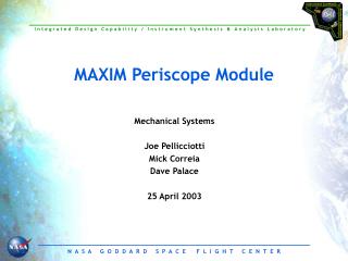
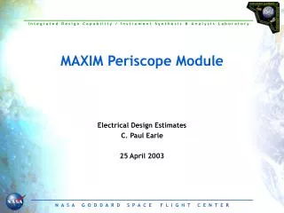
MAXIM Periscope Module Optics Dennis Charles Evans 25 April 2003
30 cm Mirror Parameters 2,10, and 30 cm TRADE STUDY TBD Mirror surface • Active area is 30 cm long by either 2,10 or 30 cm wide- so THREE different types of mirror modules for a trade study • Surface figure requirement: l/200 rms (at 633nm) • Mirror mass must be minimized • Surface Figure and Micro-roughness indicate a stable glass substrate such as ULE, ultra low expansion glass • For Baseline, width was set at 20 cm so metallic silicon could be used.
MAXIM Pathfinder IMDC Study May 2002 20,000 km 1 km Science Phase #2 High Resolution (100 nas) ATAN 0.5/20000 = 5.156620 arc sec
Collector Area • Collecting Area Each Unit is a collection of 2 sets of 4 mirrors on one common bench 30 × SIN 1 = 0.52357219311850536 cm projected width 0.52357219311850536 ×20 = 10.471443862370108 cm2 • Each 20 cm wide set has 10.47 cm2 collecting area • Goal is to have 1000 cm2 area • Hub= 6 units (12 sets) [ 48 mirrors] • Satellite= 25 (4 sets) [400 mirrors] ((25 × 4)+12) × 10.46 = 1172.64 ((25 × 4)+12) × 8.9286 = 1000.0031999999998 • 8.9286 ÷ 0.52357219311850536 = 17.053235670938506 Clear Width • 28 × SIN 1 = 0.48866738024393832 • 0.48866738024393832×18.272 = 8.92893037181724 • Mirrors Physical: 30 cm long and 20 cm wide • Clear Footprint: 28 cm long and 18.272 cm wide
Aperture Locations at 20,000 and 500 km Focal LengthZEMAX Configurations Location_20000 Location_500 1 0 10 1 0 0.25 2 60 11.8 2 60 0.295 3 120 13.9 3 120 0.3475 4 180 16.4 4 180 0.41 5 240 19.4 5 240 0.485 6 300 22.9 6 300 0.5725 7 0 27 7 0 0.675 8 60 31.9 8 60 0.7975 9 120 37.6 9 120 0.94 10 180 44.4 10 180 1.11 11 240 52.3 11 240 1.3075 12 300 61.8 12 300 1.545 13 0 72.9 13 0 1.8225 14 60 86 14 60 2.15 15 120 101.5 15 120 2.5375 16 180 120 16 180 3 17 240 141.3 17 240 3.5325 18 300 166.7 18 300 4.1675 19 0 196.7 19 0 4.9175 20 60 232.1 20 60 5.8025 21 120 274.9 21 120 6.8725 22 180 323.2 22 180 8.08 23 240 381.4 23 240 9.535 24 300 450.1 24 300 11.2525 25 0 531.1 25 0 13.2775 26 0 0 26 0 0
18 13 14 12 7 8 6 1 2 26 3 5 4 9 11 10 15 17 16 Aperture Locations (central area)
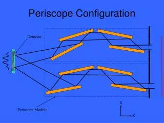
Optical Layout OPD R R (F2+R2)^0.5 F OPD/R = R/(F2+R2)^0.5 OPD=R2/(F2+R2)^0.5
Sample Mirror Arrangement (10° example) Using RTL to calculate central ray path Delay Line Shift of 1 micron = 698 A Path Difference
Total Optical Path Differences Total Optical Path Difference (meters) R=13.2775 ; F=500000 ; OPD=(R*2)÷((R*2)+(F*2))*0.5 ; OPD 0.00035258401237568448 (352584 nm) R=.25 ; F=500000 ; OPD=(R*2)÷((R*2)+(F*2))*0.5 ; OPD 1.2499999999998436E¯7 (125 nm) Delay Line Sensitivity 352584 ÷ 69.8 = 5051.34670487106 units of 0.1 micron = 505 microns = 0.000505 meters
Airy Diffraction “Rings” for 500 km OPD=31.25A 20000km OPD=1250A 500km
Interference FringesPathlength Differences 1 wavelength = 1 nm (10 Angstroms) 0.5 nm A D D=0.0000005 mm/TAN 5.156620/3600. = 0.020000 mm or 50 lines/mm
Configuration 1 2 3 4 5 6 7 8 9 10 11 12 13 14 15 16 19 22 25
Configuration 1 2 3 4 5 6 7 8 9 10 11 12 13 14 15 16 17 19 22 25
Configuration 1 2 3 4 5 6 7 8 9 10 11 12 13 14 15 16 17 18 19 22 25
Configuration 1 2 3 4 5 6 7 8 9 10 11 12 13 14 15 16 17 18 19 20 22 25
Configuration 1 2 3 4 5 6 7 8 9 10 11 12 13 14 15 16 17 18 19 20 21 22 25
Configuration 1 2 3 4 5 6 7 8 9 10 11 12 13 14 15 16 17 18 19 20 21 22 23 25
Configuration 1 2 3 4 5 6 7 8 9 10 11 12 13 14 15 16 17 18 19 20 21 22 23 24 25
Polychromatic Wavelengths For an 0.8A bandwidth and a center wavelength of 10A, the coherence length (resonance length) is approximately 125 A.
Configuration 1 2 3 4 5 6 7 8 9 10 11 12 13 14 15 16 17 18 19 20 21 22 23 24 25