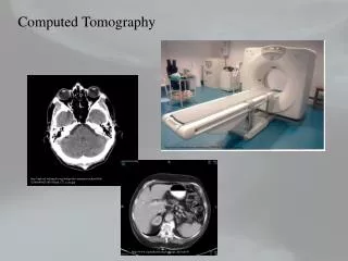

Computed Tomography
E N D
Presentation Transcript
Computed Tomography Diego Dreossi Silvia Pani University of Trieste and INFN, Trieste section
Summary • Computed Tomography • Purpose • How does it work? • CT reconstruction • Filtered backprojection • Synchrotron radiation CT • MicroCT at the SYRMEP beamline • Further applications
The goal • To provide a three-dimensional information (depth of the structures/organs) • To provide information about the attenuation coefficient (tissue characterization)
From planar imaging… to CT Source: University of Arkansas Medical School http://anatomy.uams.edu/HTMLpages/anatomyhtml/xraythorax.html
How does it work? • Laminar beam and laminar detector • The object/patient is rotated in front of the beam • During the rotation, planar images (projections) are acquired at different angles • The matrix of acquired data is called SINOGRAM: each line of the sinogram corresponds to a projection at a given angle • A map of the attenuation coefficients is reconstructed from the sinogram by means of proper algorithms
Image acquisition • The line integral of the attenuation coefficient determines the attenuation along each X-ray path
y v P(t) t F[P(t)] u x F(u,v) f(x,y) X-rays Image reconstruction: backprojection • Purpose: obtaining the distribution function f(x,y) given a complete set of projections P(q,t) • Fourier slice theorem: the FT of a projection P(q,t) corresponds to a sampling of the FT of f(x,y) along a line tilted by an angle q
v u Filtered backprojection • Each pixel of the matrix is reconstructed by summing up all projections crossing it • But: oversampling for low frequencies! Filtering: each transformed projection is multiplied by a function reducing the contribution of low frequencies
Filtered backprojection • Ramp filter (RamLak): enhancement of high frequencies noise • Gen-Hamming, Shepp-Logan: enhancement of intermediate frequencies • Convolution theorem convolution in the direct space as an alternative to multiplication in the Fourier space
q+180° q q q+180° The advantages of SR CT – I • Parallel beam: • an acquisition across 180 degrees provides all necessary information (lower dose – shorter acquisition time) • simplified reconstruction algorithms divergent beam parallel beam
The advantages of SR CT – II • Monochromatic beam: • No beam hardening artifacts • Possibility of reconstructing true attenuation coefficients tissue characterization
MicroCT at the SYRMEP beamline - I sample BEAM CCD detector rotational stage
90 degrees 140 degrees 0 degrees MicroCT at the SYRMEP beamline - II • A projection = a 2048 * 300 matrix • A height h is chosen • A line at height h is extracted from each projection and a sinogram is formed
MicroCT at the SYRMEP beamline - III • The sinogram is trimmed in order to have the center of rotation coincident to the center of the matrix
= -ln ( )/I0 MicroCT at the SYRMEP beamline - IV • The sinogram is transformed in order to obtain line integrals of the attenuation coefficients
MicroCT reconstructions at the SYRMEP beamline - V • Each line of the logarithmic sinogram is filtered • The final image is obtained by means of a backprojection Volume rendering
Volume rendering • 2-d images are stacked • The 3-d structure of the object is visualized
A possible application: sintered replicas of biological samples • Why? • Tool for enhanced visualization • Used in mechanical tests to assess the bone architecture load bearing capabilities • Tests on biological samples cannot be repeated! • How? • Built by rapid prototyping in a relatively homogeneous and well characterized material
Selected laser sintering • The object is defined by means of a CAD file • Layer Manufacturing Technology (LMT) • Parts are manufacturing layer by layer from polyamide powder with a CO2 laser • Complex structures, such as the trabecular architecture, can be built