COMPUTED TOMOGRAPHY
COMPUTED TOMOGRAPHY. CHAPTER 33. FUNDAMENTALS . Creating a cross-sectional tomographic plane of any body part A patient is scanned by an x-ray tube rotating around the body A detector assembly measures the radiation exiting the patient. FUNDAMENTALS. Exiting radiation: Primary data


COMPUTED TOMOGRAPHY
E N D
Presentation Transcript
COMPUTED TOMOGRAPHY CHAPTER 33
FUNDAMENTALS • Creating a cross-sectional tomographic plane of any body part • A patient is scanned by an x-ray tube rotating around the body • A detector assembly measures the radiation exiting the patient
FUNDAMENTALS • Exiting radiation: Primary data • Primary data is collected by detectors • The computer compiles and calculates the data based on preselected alogorithm and an image is
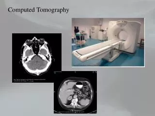
IMAGE • Each image is displayed in an axial form (usually) • The images are displayed on a cathode ray tube
CT • Conventional Radiographs: Frequently body structures are superimposed • In CT: A tightly collimated x-ray beam is directed thought the patient from different angles – “cross sectional image” • Essentially eliminating superimposition of body structures
CT • Claim to fame: Exceptional Contrast Resolution
Contrast resolution = differentiation of densities, capable of differentiating among tissues with similar densities
CT • Due to the reduction in amount of scattered radiation • Reducing over lapping structures and 2 collimators • Digitized image: because of this numerous image manipulation techniques can be used to enhance and optimize the diagnostic information. • Window/Level, Axial, Sagittal, Coronal
Third Generation • Fan-shaped x-ray beam • 960 detectors opposite the x-ray tube • Complete 360 degree rotation • Rotate/Rotate movement • One rotation = one slice • Second data acquisition could be made as the tube and detectors move in the opposite direction. • Time reduced to 1 sec per slice
Fourth Generation • Developed in 1980’s • Fixed ring of as many as 4800 detectors, completely surrounding the patient, Rotate only movement • Rotating x-ray tube provides short bursts of radiation • Detectors collect the remnant radiation to reconstruct into an image • 1 minute for multiple slices
Modern Scanners • No longer categorized into Generations • Contemporary CT scanners are either third or fourth generation designs • Scanners are categorized by tube and detector movement • Slip Ring Technology: connects generator with tube (no cables)
Technical Aspects • Optimum imaging: patient/area of interest and gantry are perpendicular to each other • Tube rotates around the patient, irradiating the area of interest. • Detectors measure the transmitted x-ray values, covert them in to an electric signal, and relay the signal to the computer.
Raw Data • The remnant radiation that is converted into an electrical signal values are called projections, scan profiles or raw data • Raw data is collected and digitized • This process assigns a whole number to each signal. • The value assigned is directly proportional to the strength of the signal.
Digital Image • Array of numbers arranged in a grid of rows and columns called a matrix. • Single square, or picture element, with in the matrix is called a pixel. • Slice thickness gives the pixel and added dimension called the volume element, or voxel
Voxel • Each pixel in the image corresponds to the volume of tissue in the body section being imaged. • The voxel volume is a product of the pixel area and slice thickness
Hounsfield units • Each pixel within the matrix is assigned a number that is related to the linear attenuation coefficient of the tissue within each voxel • These are CT numbers or Hounsfield units.
Hounsfield units • Defined: A relative comparison of x-ray attenuation of a voxel of tissue to an equal volume of water. • Water is used because it is in abundance in the body and has a uniform density • Water is assigned an arbitrary value of 0
CT numbers • Tissue denser than water are given positive CT numbers • Tissue with less density than water are assigned negative CT numbers • The scale of CT numbers ranges from -1000 for air to +3,000 for dense bone
Displaying the image • On the CRT, each pixel within the image is assigned a level of gray • The gray level assigned to each pixel corresponds to the CT number or Hounsfield units for that pixel
System Components • Computer, Gantry &Table & Operator’s Console • Computer – provides the link between the CT technologist and the other components of the imaging system
Computer • The computer has four basic functions: • Control of data acquisition • Image reconstruction • Storage of image data • Image display
Array Processor • Raw Data is sent to the array processor • Array processor only performs algorithm calculations. • Applies desired filters to raw data.
Gantry • Gantry is a circular device that houses the Data Acquisition system (DAS) • Tube • Detectors • Filters • Collimators • Analog-to –Digital Converter (ADC)
Gantry • Can be tilted forward or backward up to 30 degrees to compensate for body part angulation. • The opening within the center of the gantry is termed the aperture
CT Tubes • X-ray tube for CT is similar in design to the conventional radiography tube, • but is specially designed to handle and dissipate excessive heat units – much higher heat loading • Ceramic target backing • Decreases tube weight
Detectors • Function as image receptors for remnant radiation • then converts the measurement into an electrical signal proportional to the radiation intensity. • Two basic detector types are used: Scintillation (solid state) and Ionization (xenon gas) detectors.
Detectors • Used to record photon activity • Materials include: cadmium tungstate, cesium iodide, gadolinium or yttrium
Table • Automated device linked to the computer and gantry • Designed to move in increments after every scan according to the technologists scan program • Accurate and reliable table movements is vital to image quality and accuracy • Has weight limits
Operator’s Console • Where the technologist controls the scanner • Keyboard • graphic monitor • Mouse
Display Monitor • For the CT image to be displayed monitor in a recognizable form, the digital CT data must be converted into a gray-scale image • Each digital CT number is the matrix is converted into an analog voltage
Image Display • The brightness value of the gray-scale image correspond to the pixels and CT numbers of the digital data they represent • Because the image is digital image manipulation can be performed
FOV • The field of view determines the amount of data to be displayed on the monitor
Image manipulation • Most common: windowing or gray-level mapping • This technique allows the technologist to alter the contrast of the displayed image • by adjusting the window width and window level.
Windowing • Window width: is the range of CT numbers that are used to map signals into shades of gray • Wide/Narrow or Long/Short • Window level: determines the midpoint of the range of gray levels to be displayed • Darker or Lighter
Image manipulation • Multiplanar reconstruction or MPR • Ability to reconstruct axial images into coronal, sagittal or oblique body planes