Computed Tomography
Computed Tomography. Radiography: 3 problems 3D collapsed to 2D Low soft-tissue contrast Not quantitative. X-Ray CT solves these problems (but costs much more $$). The mathematics behind X-Ray CT (reconstruction from projections) applies to other modalities as well (PET, Spect, etc).


Computed Tomography
E N D
Presentation Transcript
Radiography: 3 problems • 3D collapsed to 2D • Low soft-tissue contrast • Not quantitative
The mathematics behind X-Ray CT (reconstruction from projections) applies to other modalities as well (PET, Spect, etc).
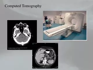
Computed tomography (CT) is in its fourth decade of clinical use and has proved valuable as a diagnostic tool for many clinical applications, from cancer diagnosis trauma to osteoporosis screening. • CT was the first imaging modality that made possible to probe the inner depths of the body, slice by slice.
Since 1972, when first head CT scanner was introduced, CT has matured greatly and gained technological sophistication. • The first CT scanner, an EMI Mark 1, produced images with 80 x 80 pixel resolution (3-mm pixels), and each pair of slices required approximately 4.5 mm-of scan time and 1.5minutes of reconstruction time.
Because of the long acquisition times required for the early scanners and the constraints of cardiac and respiratory motion, it was originally thought that CT would be practical only for head scans.
CT is one of the many technologies that was made possible by the invention of computer. • The clinical potential of CT became obvious during its early clinical use, and the excitement forever solidified the role of computers in medical imaging.
Recent advances in acquisition geometry, detector technology, multiple detector arrays, and x-ray tube design have led to scan times now measured in fractions of a second. • Modern computers deliver computational power that allows reconstruction of the image data essentially in real time.
The invention of the CT scanner earned Godfrey Hounsfield of Britain and Allan Cormack of the United States the Nobel Prize for Medicine in 1979. • CT scanner technology today is used not only in medicine but in many other industrial applications, such as nondestructive testing and soil core analysis.
BASIC PRINCIPLES • The mathematical principles of CT were first developed by Radon in 1917. • Radon’s treatise proved that an image of an unknown object could be produced if onehad an infinite number of projections through the object.
Although the mathematical details are beyond the scope of this text, we can understand the basic idea behind tomographic imaging with an example taken from radiography. • With plain film imaging, the three-dimensional (3D) anatomy of the patient is reduced to a two-dimensional (2D) projection image. • The density at a given point on an image represents the x-ray attenuation properties within the patient along a line between the x-ray focal spot and the point on the detector corresponding to the point on the image.
With a conventional radiograph of the patient’s anatomy, information with respect to the dimension parallel in the x-ray beam is lost. • This limitation can be overcome, at least for obvious structures, by acquiring both a posteroanterior (PA) projection and a lateral projection of the patient.
For example, the PA chest image yields information concerning height and width, integrated along the depth of the patient, and the lateral projection provides information about the height and depth of the patient integrated over the width dimension.
For objects that can be identified in both images, such as a pulmonary nodule on PA and lateral chest radiographs, the two films provide valuable location informarion. • For more complex or subtle pathology, however, the two projections are not sufficient.
Imagine that instead of just two projections, a series of 360 radiographs were acquired at 1-degree angular intervals around the patient’s thoracic cavity. • Such a set of images provides essentially the same data as a thoracic CT scan.
However, the 360 radiographic images display the anatomic information in a way that would be impossible for a human to visualize: • cross-sectional images. • If these 360 images were stored into a computer, the computer could in principle reformat the data and generate a complete thoracic CT examination.
The tomographic image is a picture of a slab of the parient’s anatomy. • The 2D CT image corresponds to a 3D section of the patient, so that even with CT, three dimensions arecompressed into two. • However, unlike the case with plain film imaging, the CT slice-thickness is very thin (1 to 10 mm) and is approximately uniform.
The 2D array of pixels (short for picture elements) in the CT image corresponds to an equal number of 3D voxels (volume elements) in the patient. • Voxels have the same in-plane dimensions as pixels, bur they also include the slice thickness dimension.
Each pixel on the CT image displays the average x-ray attenuation properties of the tissue in the corresponding voxel.
Tomographic Acquisition • A single transmission measurement through the patient made by a single detector at a given moment in time is called a ray. • A series of rays that pass through the patient at the same orientation is called a projection or view.
There are two projection geometries that have been used in CT imaging.
The more basic type is parallel beam geometry, in which all of the rays in a projection are parallel to each other. • In fan beam geometry, the rays at a given projection angle diverge and have the appearance of a fan. • All modern GT scanners incorporate fan beam geometry in the acquisition and reconstruction process.
The purpose of the CT scanner hardware is to acquire a large number of transmission measurements through the patient at different positions. • The acquisition of a single axial CT image may involve approximately 800 rays taken at 1,000 different projection angles, for a total of approximately 800,000 transmission measurements.
Before the axial acquisition of the next slice, the table that the patient is lying on is moved slightly in the cranial-caudal direction (the “x-axis” of the scanner), which positions a different slice of tissue in the path of the x-ray beam for the acquisition of the next image.
Tomographic Reconstruction • Each ray that is acquired in CT is a transmission measurement through the patient along a line, where the detector measures an x-ray intensity, It. • The unattenuated intensity of the x-ray beam is also measured during the scan by a reference detector, and this detects an x-ray intensity Io.
The relationship between Io and It, is given by he following equation: • where t is the thickness of the patient along the ray and m is the average linear attenuation coefficient along the ray • Notice that It and Ioare machine-dependent values, but the product mtis an important parameter relating to the anatomy of the patient along a given ray.
When the equation is rearranged, the measured values It and Iocan be used to calculate the parameter of interest: • where In is the natural logarithm (to base e, e = 2.78 .). • t ultimately cancels out, and the value m for each ray is used in the CT reconstruction algorithm.
This computation, which is a preprocessing step performed before image reconstruction, reduces the dependency of the CT image on the machine-dependent parameters, resulting in an image that depends primarily on the patient’s anatomic characteristics. • This is very much a desirable aspect of imaging in general, and the high clinical utility of CT results, in part, from this feature.
By comparison, if a screen-film radiograph is underexposed (Io is too low) it appears cool white, and if it is overexposed (Io too high) it appears too dark. • The density of CT images is independent of Io, although the noise in the image is affected.
After preprocessing of the raw data, a CT reconstruction algorithm is used to produce the CT images. • There are numerous reconstruction strategies; however, filtered backprojection reconstruction is most widely used in clinical CT scanners.
The backprojection method builds up the CT image in the computer by essentially reversing the acquisition steps. • During acquisition, attenuation information along a known path of the narrow x-ray beam is integrated by a detector. • During backprojection reconscruction, the m value for each ray is smeared along this same path in the image of the patient.
Data acquisition in computed tomography (CT) involves making transmission measurements through the object at numerous angles around the object (left). The process of computing the CT image from the acquisition data essentially reverses the acquisition geometry mathematically (right). Each transmission measurement is backprojected onto a digital matrix. After backprojection, areas of high attenuation are positively reinforced through the backprojection process whereas other areas are not, and thus the image is built up from the large collection of rays passing through it.
As the data from a large number of rays are backprojected onto the image matrix, areas of high attenuation tend to reinforce each other, and areas of low attenuation also reinforce, building up the image in the computer.
First Generation: Rotate/Translate, Pencil Beam • CT scanners represent a marriage of diverse technologies, including • computer hardware, • motor control systems, • x-ray detectors, • sophisticated reconstruction algorithms, and • x-ray tube/generator systems.
The first generation of CT scanners employed a rotate/translate, pencil beam system (Fig. 13-5).
Only two x-ray detectors were used, and they measured the transmission of x-rays through the patient for two different slices. • The acquisition of the numerous projections and the multiple rays per projection required char the single detector for each CT slice be physically moved throughout all the necessary positions.
This system used parallel ray geometry. • Starting at a particular angle, the x-ray tube and detector system translated linearly across the field of view (FOV), acquiring 160 parallel rays across a 24-cm FOV. • When the x-ray tube/detector system completed its translation, the whole system was rotated slightly, and then another translation was used to acquire the 160 rays in the next projection. • This procedure was repeated until 180 projections were acquired at 1-degree intervals. • A total of 180 x 160 = 28,800 rays were measured.
First-generation (rotate/translate) computed tomography (CT). The x-ray tube and a single detector (per CT slice) translate across the field of view, producing a series of parallel rays. The system then rotates slightly and translates back across the field of view, producing ray measurements at a different angle. This process is repeated at 1-degree intervals over 180 degrees, resulting in the complete CT data set.
As the system translated and measured rays from the thickest part of the head to the area adjacent to the head, a huge change in x-ray flux occurred. • The early detector systems could not accommodate this large change in signal, and consequently the patient’s head was pressed into a flexible membrane surrounded by a water bath. • The water bath acted to bolus the x-rays so that the intensity of the x-ray beam outside the patients head was similar in intensity to that inside the head.
The detector also had a significant amount of “afterglow,” meaning that the signal from a measurement taken at one period of time decayed slowly and carried over into the next measurement if the measurements were made temporally too close together.
One advantage of the first-generation CT scanner was that itemployed pencil beam geometry. • Only two detectors measured the transmission of x-rays through the patient.
The pencil beam allowed very efficient scatter reduction, because scatter that was deflected away from the pencil ray was not measured by a detector. • With regard to scatter rejection, the pencil beam geometry used in first-generation CT scanners was the best.
Second Generation: Rotate/Translate, Narrow Fan Beam • The next incremental improvement to the CT scanner was the incorporation of a linear array of 30 detectors. • This increased the utilization of the x-ray beam by 30 times, compared with the single detector used per slice in first-generation systems.
A relatively narrow fan angle of 10 degrees was used. • In principle, a reduction in scan time of about 30-fold could be expected. • However, this reduction time was not realized, because more data (600 rays X 540 views = 324,000 data points) were acquired to improve image quality. • The shortest scan time with a second-generation scanner was 18 seconds per slice, 15 times faster than with the first-generation system.
Incorporating an array of detectors, instead of just two, required the use of a narrow fan beam of radiation. • Although a narrow fan beam provides excellent scatter rejection compared with plain film imaging, it does allow more scattered radiation to be detected than was the case with the pencil beam used in first-generation CT.
Pencil beam geometry makes inefficient use of the x-ray source, but it provides excellent x-ray scatter rejection. X-rays that are scattered away from the primary pencil beam do not strike the detector and are not measured. Fan beam geometry makes use of a linear x-ray detector and a divergent fan beam of x-rays. X-rays that are scattered in the same plane as the detector can be detected, but x-rays that are scattered out of plane miss the linear detector array and are not detected. Scattered radiation accounts for approximately 5% of the signal in typical fan beam scanners. Open beam geometry, which is used in projection radiography, results in the highest detection of scatter. Depending on the dimensions and the x-ray energy used, open beam geometries can lead to four detected scatter events for every detected primary photon (s/p=4).
Third Generation: Rotate/Rotate, Wide Fan Beam • The translational motion of first- and second-generation CT scanners was a fundamental impediment to fast scanning. • At the end of each translation, the motion of the x-ray tube/detector system had to be stopped, the whole system rotated, and the translational motion restarted.