Computed Tomography I
Computed Tomography I. Basic principles Geometry and historical development. Basic principles. Mathematical principles of CT were first developed in 1917 by Radon Proved that an image of an unknown object could be produced if one had an infinite number of projections through the object.

Computed Tomography I
E N D
Presentation Transcript
Computed Tomography I Basic principles Geometry and historical development
Basic principles • Mathematical principles of CT were first developed in 1917 by Radon • Proved that an image of an unknown object could be produced if one had an infinite number of projections through the object
Basic principles (cont.) • Plain film imaging reduces the 3D patient anatomy to a 2D projection image • Density at a given point on an image represents the x-ray attenuation properties within the patient along a line between the x-ray focal spot and the point on the detector corresponding to the point on the image
Basic principles (cont.) • With a conventional radiograph, information with respect to the dimension parallel to the x-ray beam is lost • Limitation can be overcome, to some degree, by acquiring two images at an angle of 90 degrees to one another • For objects that can be identified in both images, the two films provide location information
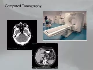
Tomographic images • The tomographic image is a picture of a slab of the patient’s anatomy • The 2D CT image corresponds to a 3D section of the patient • CT slice thickness is very thin (1 to 10 mm) and is approximately uniform • The 2D array of pixels in the CT image corresponds to an equal number of 3D voxels (volume elements) in the patient • Each pixel on the CT image displays the average x-ray attenuation properties of the tissue in the corrsponding voxel
Tomographic acquisition • Single transmission measurement through the patient made by a single detector at a given moment in time is called a ray • A series of rays that pass through the patient at the same orientation is called a projection or view • Two projection geometries have been used in CT imaging: • Parallel beam geometry with all rays in a projection parallel to one another • Fan beam geometry, in which the rays at a given projection angle diverge
Acquisition (cont.) • Purpose of CT scanner hardware is to acquire a large number of transmission measurements through the patient at different positions • Single CT image may involve approximately 800 rays taken at 1,000 different projection angles • Before the acquisition of the next slice, the table that the patient lies on is moved slightly in the cranial-caudal direction (the “z-axis” of the scanner)
Tomographic reconstruction • Each ray acquired in CT is a transmission measurement through the patient along a line • The unattenuated intensity of the x-ray beam is also measured during the scan by a reference detector
Reconstruction (cont.) • There are numerous reconstruction algorithms • Filtered backprojection reconstruction is most widely used in clinical CT scanners • Builds up the CT image by essentially reversing the acquistion steps • The value for each ray is smeared along this same path in the image of the patient • As data from a large number of rays are backprojected onto the image matrix, areas of high attenutation tend to reinforce one another, as do areas of low attenuation, building up the image
1st generation: rotate/translate, pencil beam • Only 2 x-ray detectors used (two different slices) • Parallel ray geometry • Translated linearly to acquire 160 rays across a 24 cm FOV • Rotated slightly between translations to acquire 180 projections at 1-degree intervals • About 4.5 minutes/scan with 1.5 minutes to reconstruct slice
1st generation (cont.) • Large change in signal due to increased x-ray flux outside of head • Solved by pressing patient’s head into a flexible membrane surrounded by a water bath • NaI detector signal decayed slowly, affecting measurements made temporally too close together • Pencil beam geometry allowed very efficient scatter reduction, best of all scanner generations
2nd generation: rotate/translate, narrow fan beam • Incorporated linear array of 30 detectors • More data acquired to improve image quality (600 rays x 540 views) • Shortest scan time was 18 seconds/slice • Narrow fan beam allows more scattered radiation to be detected
3rd generation: rotate/rotate, wide fan beam • Number of detectors increased substantially (to more than 800 detectors) • Angle of fan beam increased to cover entire patient • Eliminated need for translational motion • Mechanically joined x-ray tube and detector array rotate together • Newer systems have scan times of ½ second
Ring artifacts • The rotate/rotate geometry of 3rd generation scanners leads to a situation in which each detector is responsible for the data corresponding to a ring in the image • Drift in the signal levels of the detectors over time affects the t values that are backprojected to produce the CT image, causing ring artifacts
4th generation: rotate/stationary • Designed to overcome the problem of ring artifacts • Stationary ring of about 4,800 detectors
3rd vs. 4th generation • 3rd generation fan beam geometry has the x-ray tube as the apex of the fan; 4th generation has the individual detector as the apex
5th generation: stationary/stationary • Developed specifically for cardiac tomographic imaging • No conventional x-ray tube; large arc of tungsten encircles patient and lies directly opposite to the detector ring • Electron beam steered around the patient to strike the annular tungsten target • Capable of 50-msec scan times; can produce fast-frame-rate CT movies of the beating heart
6th generation: helical • Helical CT scanners acquire data while the table is moving • By avoiding the time required to translate the patient table, the total scan time required to image the patient can be much shorter • Allows the use of less contrast agent and increases patient throughput • In some instances the entire scan be done within a single breath-hold of the patient
7th generation: multiple detector array • When using multiple detector arrays, the collimator spacing is wider and more of the x-rays that are produced by the tube are used in producing image data • Opening up the collimator in a single array scanner increases the slice thickness, reducing spatial resolution in the slice thickness dimension • With multiple detector array scanners, slice thickness is determined by detector size, not by the collimator