Download

1 / 47
500 likes | 824 Views
Essentials of pleural cavity drainage. Department of General, Oncological and Thorax Surgery Medical University of Lodz Head: prof. dr hab. med. Marian Brocki. Authors: Robert Gruda MD, Robert Stolarek MD.

E N D
Essentials of pleural cavity drainage Department of General, Oncological and Thorax Surgery Medical University of Lodz Head: prof. dr hab. med. Marian Brocki Authors: Robert Gruda MD, Robert Stolarek MD
Drainage or puncture of pleural cavity is relatively common surgery procedure at the thoracic surgery wards or general, ICU, internal or oncology departments • It is a simple procedure but usually multiple minor problems are encountered
History • VI century BC. – Hippocrates – described open pleural drainage and the use of metal drain in pleural empyema • XV century AC. – Celsius – described rib removal, tocar use and metal pipe for pleural drainage • 1860 – Hunter – applied hypodermal needle for pleural drainage • 1875 – Playfair – introduced drainage with underwater valve for pleural empyema therapy • 1876 – Hewett – described closed system for continuous drainage in the therapy of pleural empyema • 1910 – Robinson – introduced vacuum into chest drainage with the use of sucking pump • 1922 – Lilienthal – introduced closed vacuum pleural drainage in patient after the chest surgery • 1945 – introduction of three bottle sets • 1986 – introduction of single use sets
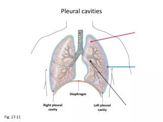
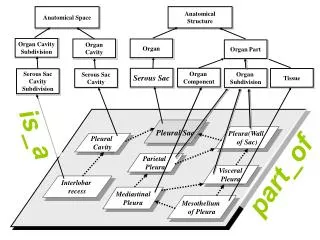
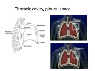
Anatomy and physiology of pleura cavity • Pleural cavity is a bilateral serum space inside the chest limited by parietal pleura, lining chest walls and visceral pleura which is lining lungs • Under physiological conditions parietal and visceral pleura form capillary space 7 – 24 m wide, containing small amount • Under normal conditions visceral fluid is produced at the approximate rate 0,01 ml/kg m.c. /h • The elastic recoil of chest wall maintains negative pressure inside the thorax cavity and the constant expansion of the lungs. • Chest intrusion, accumulation of fluid or air inside pleural cavity abolish the negative pressure inside leading to the decrease of lung volume and the increase of pleural volume. • Pleural drainage is necessary for the restoration of physiological conditions
Pleural cavity drainage • open – when pleural cavity directly connects with the atmosphere (used rarely, mainly in case of chronic pleural empyema) • Closed – when pleura is separated from the atmosphere with drainage set • passive – without vacuum • active – with vacuum
Indications for pleural drainage • pneumothorax • Pleural fluid (exudation, empyema, hematoma, lymph) • Postoperative pleural drainage • Pleurobronchial fistula
Contradiction for pleural drainage There are no unconditional contradictions for pleural drainage
pneumothorax The presence of gas in pleural cavity • Internal (via bronchial wall) • External (via chest wall) • Spontaneous • Primary (no lung pathology) • Secondary (the presence of lung pathology) • Traumatic • Non-iatrogenic (open/closed trauma) • Iatrogenic (after BAC of the lungs, Mediastinum, subcalvucular venosection, etc.) • entire • partial
Pleural drainage systems System of pleural drainage includes: • Drainage systems • Pleural drain • connectors • Connecting drainage • Bottle system • Drainage bottle • Underwater valve • Reduction bottle
Drainage systems • No toxicity • No allergy reaction • No agitation • Should be flexible and at the same time stiff enough to avoid collapse • Should be transparent • X ray marker incorporated into the wall • The terminal lumen should be the same as drainage diameter
Small drainage These are plastic small drainages up to 10F in size, with a needle inside for penetration or outside for drainage insertion . Thin drainage are used in diagnostics and the therapeutical pleurocentesis, surgical anesthesia and pericardiocentesis. They are fragile, can be stuck easily, may break and therefore are not suitable for routine pleural drainage.
Medium drainage They are vinyl drainages of 10-20F size with a lancet inside. The presence of stiff lancet inside allows for the insertion from a tiny hole in skin surface. These drainage is especially useful in the drainage of encapsulated containers and lung apex drainage from supraclavicular access.
Large drainage Vinyl drainage of 20-36F size may include a lancet. They are inserted usually during toracotomy and their narrowed ending makes the insertion through the incision canal easier. Insertion of drainage into the closed chest required more force and the expansion of the tissues with a tool or a finger.
Connecting drainage This is a drainage between pleural drainage and the drainage bottle. It has to be transparent, light, flexible, resistant to collapse and breakings. Optimal size of connecting drainage determines its optimal resistance to the flow: length 1.8 m., internal diameter 9.5 – 12 mm
Drainage connections There are various types of connectors for different size diameter drainage. Their fixation should maintain tight sealed connection, good visibility inside the connector and the drainage as well as the safety of the connection
Drainage bottles Features of drainage bottles • Sealed thight • Quality of connection • Resistance to incidental breakage • Light, stiff material resistant to collapse • Construction preventing reverse assembly
Passive drainage Passive drainage a gravity propelled drainage including one bottle. It is the most crude type of pleural drainage. Its function involves containing and underwater valve. The valve allows for the removal of the air from the plural cavity and prevent form the sucking of the air. Intrusion of the air into the pleural cavity is blocked by underwater valve.
Passive drainage The drainage pipe should be submerged 2 cm under water. Lower submersion may lead to the loss of tight assembly, increased air flow resistance. Lack of alternated fluid levels indicates stucked flow, flexed connection, fluid accumulation in connecting drainage or the complete expansion of the lung. The set should be placed below the chest level to maintain pressure gradient.
Two bottle passive drainage This set includes main bottle and the bottle with submerged valve. Blood or exudative fluid accumulates in the main bottle whereas the air gets into the other. The drainage allows for freely air removal. The pressure in the main bottle is always equal to the pressure inside the pleural cavity.
Two bottle active drainage This is the most common active sucking system. It included submerges valve and the bottle regulating the suction power.
Three bottle active drainage This set includes main bottle, submerged valve and the bottle for the regulation of suction power. The reduction bottle decreases the sub pressure generated by suction tools.
Four bottle active drainage Fuor bottle system includes additional bottle with submerges valve connected to three bottle set. Air pressure valve of the additional bottle protects from pressure increase in case of the failure of suction providing the information on the current pressure in the pleural cavity.
Features of vacuum devices • The maintenance of the lowered pressure in the range between 0 and 60 cm H2O • The availability of high flow (20 l/min) at the pressure – 10 cm H2O • The maintenance of the negative pressure in the system • The removal of drained air into the atmosphere due to air removal drain even if sucking does not operate
Other drainage systems Pleural-peritoneal valve of Denver type– unidirectional valve for fluid trafficking from pleural to peritoneal cavity in patients with recurrent accumulation of pleural fluid without the option of complete lung expansion
Other drainage systems Heimlich valve – invented in 1968 as single or double płatowa valve, especially useful in patient transportation
Other drainage systems The set for ambulatory pleural drainage– it includes plastic sack with płatkową valve and excess air valve. It may be carried by the patients similarly to the urine containers. It is used in the therapy of chronic pleurobronchial fistulae and recurrent exudative pleuritis
Access to pleural cavity Anterior access– commonly II or III intercostal space in middle anterior clavicle or axillar line. Most routine in pneumothorax.
Access to pleural cavity Lateral access – the drainage is place in from IV to VI intercostal space in anterior or middle axillar line. The drainage ending at the time of air evacuation is directed rostrally (towards apex) whereas at the fluid evacuation caudally and downwards (towards above diaphragm).
Access to pleural cavity Suprascapular access– second intercostal space below the scapula in posterior scapular line. For apex limited pathology only.
Access to pleural cavity Posterior access – used for the drainage of encapsulated purulent container in the dorsal region below the scapula. It is guided by CT or USG.
Choose site • Trójkąt bezpieczeństwa Suture tube to chest Explore with finger Place tube with clamp