Download
1 / 49
550 likes | 799 Views
Chapter 7. In chapter 6 , we noted that an important attribute of inductors and capacitors is their ability to store energy. In this chapter , we are going to determine the currents and voltages that arise when energy

E N D
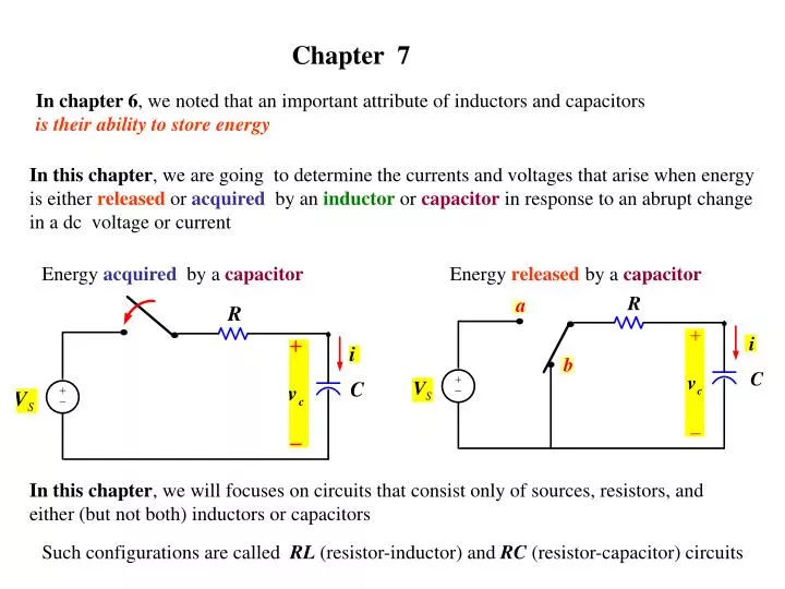
Chapter 7 In chapter 6, we noted that an important attribute of inductors and capacitors is their ability to store energy In this chapter, we are going to determine the currents and voltages that arise when energy is either released or acquired by an inductor or capacitor in response to an abrupt change in a dc voltage or current Energy acquired by a capacitor Energy releasedby a capacitor In this chapter, we will focuses on circuits that consist only of sources, resistors, and either (but not both) inductors or capacitors Such configurations are called RL (resistor-inductor) and RC (resistor-capacitor) circuits
Our analysis of the RL and RC circuits will be divided into three phases: First Phase we consider the currents and voltages that arise when stored energy in an inductor or capacitor is suddenly released to a resistive network This happens when the inductor or capacitor is abruptly disconnected from its dc source and allowed to discharge through a resistor The currents and voltages that arise in this configuration are referred to as the natural response of the circuit to emphasize that the nature of the circuit itself , not external sources excitation determine its behavior you can think of this as when a tank of water is opened suddenly , will the water in the tank disappear instantaneously in zero second or will it takes some time no matter how small to empty the tank
Second Phase we consider the currents and voltages that arise when energy is being acquired by an inductor or capacitor due to the sudden application to a dc voltage or current source This response is referred to as the step response you can think of this as when a tank of water is being filled suddenly , will the water in the tank rise instantaneously in zerosecond or will it takes some time no matter how small for the water to rise in the tank
Third Phase The process for finding both the natural response ( First Phase ) and step response ( Second Phase )is the same thus in the third phase we will develop a general method that can be used to find the response of RL and RC circuit to any abrupt change in a dc voltage or current
7.1 The Natural Response of an RL Circuits Let the circuit shown which contain an inductor is shown Suppose the switch has been in a closed position for a long time we will define long time later For the time being long time All currents and voltages have reached a constant value Only constant or DC currents can exist in the circuit just prior to the switch’s being opened The inductor appears as a short circuit
Because the voltage across the inductive branch is zero There can be no current in either R0 or R All the source current ISappears in the inductive branch Finding the natural response requires finding the voltages and currents at any branch in the circuit after the switch has been opened.
If we let t = 0 denote the instant when the switch is opened The problem become one of finding v(t) and i(t) ( or i and v ) for t ≥ 0 For t ≥ 0 the circuit become
Deriving the Expression for the current KVL around the loop This is a first order differential equation because it contains terms involving the ordinary derivative of the unknown di/dt. The highest order derivative appearing in the equation is 1. Hence the first order We can still describe the equation further. Since the coefficients in the equation R and Lare constant that is not functions of either the dependent variable i or the independent variable t Thus the equation can also be described as an ordinary differential equation with constant coefficients
To solve the differential equation we processed as follows: Integrating both side to obtain explicit expression for i as a function of t Here t0 = 0 Based on the definition of the natural logarithm
Since the current through an indicator can not change abruptly or instanteously Were I0 is the initial current on the inductor just before the switch opened ( or in some cases closed) In the circuit above I0 = Is Therefore Which shows that the current start from initial value I0 and decreases exponentially toward zero as t increases
We derive the voltage across the resistor form direct application of Ohm’s law Note the voltage v(t) here is defined for t > 0 because the voltage across the resistor R is zero for t < 0 ( all the current Is was going through L and zero current through R) Note the voltage v(t) across the resistor and across the indicator can change instanousley or have a jump
We derive the power dissipated in the resistor or Whichever form is used, the resulting expression can be reduce to Note the current i(t) through the resistor is zero for t < 0
We derive the energy delivered to the resistor The energy deliver to the resistor is after the switch is opened because before that there was no current passing through the resistor and the voltage across it was zero
Note that just before the switch is opened the current on the indicator is IS = I0 The initial energy stored in the indictor
The significant of the time constant The coefficient at the exponential term namely R/L determine the rate at witch the exponential term in the current approaches zero The reciprocal of this ratio (L/R ) is the time constant which has the units of seconds the time constant for the R,L circuit is Seconds It is convenient to think of the time elapsed after switching in terms of integral multiple of t Example After one time constant, the maximum of the current I0 has dropped to 37% of its value
Table showing the value of exponential e-t/t for integral multiples of t Note that when the time elapsed after switching exceed five time constants The current is less than 1% of its initial value I0 Thus sometime we say that five time constant after switching has occurred, the currents and voltages have for most practical purposes reached their final values Thus with 1% accuracy along time Five or more time consent
The existence of the current in the RL circuit is momentary event and is referred to as transient response of the circuit The response that exist a long time after the switching has taken place is called steady-state response The steady-state response in the RL circuit is zero , that were the i(t) will go to as t goes to infinity
Determining the time constant The time constant can be determined as follows (1) If the RL circuit can be put as Were L is an equivalent inductor and R is an equivalent resistor Seen by the equivalent indictor Example
(2) If we know the differential equation t is the inverse of this constant Example Suppose the differential equation is given as
(2) If a trace or graph of i(t) is given Differentiating i(t) we have
7.1 The Natural Response of an RL Circuits We are going to find the currents and voltages in 1st order RL and RC circuits when a DC voltage or current is suddenly applied. Performing the Integrating
7.3 Step Response of RL and RC Circuits We are going to find the currents and voltages in 1st order RL and RC circuits when a DC voltage or current is suddenly applied. The Step Response of an RL Circuit The switch is closed at t = 0 , the task is to find the expressions for the current in the circuit and for the voltage across the inductor after the switch has been closed
After the switch has being closed, we have We can solve the differential equation similar to what we did previously with the natural response by separating the variables i and t and integrating as follows
We know separate the variables i and t Integrating both side to obtain explicit expression for i as a function of t Were I0 is the current at t = 0 and i(t) is the current at any t > 0 Performing the Integrating and the substitution of the limits When no initial current on the inductor I0 = 0
When no initial current on the inductor I0 = 0 When initial current on the inductor I0 ≠ 0 The equation for the no initial current (I0 = 0) indicate that the after the switch is closed the current will increase exponentially to its final value of Vs / R
When no initial current on the inductor I0 = 0 At one time constant t = L / R the current will be The current will reached 63% of Its final value
The rate of change of i(t) or di(t)/dt current will be The rate of change of i(t) or di(t)/dt at t = 0 ( The tangent at t=0 ) will be Which when drawn on the plot of i(t) will be as Here t = L/R therefore the slop of the tangent at t =0 is
When initial current on the inductor I0 ≠ 0 The voltage across the inductor will be Before the switch close the voltage across the inductor is zero Just after the switch close the voltage across the inductor will jump to because initial current on the inductor I0.This will make the voltage drop across the resistor after the switch was closed at t = 0+ to be RI0 → voltage drop across the inductor is (Vs-RI0) If the initial current on the inductor I0 = 0, the current will be and the voltage across the inductor will jump to Note the inductor voltage can jump however the current is not allowed to jump
When initial current on the inductor I0 ≠ 0 When no initial current on the inductor I0 = 0 When initial current on the inductor I0 ≠ 0 When no initial current on the inductor I0 = 0
Solving the differential equation when the initial current on the inductor I0 ≠ 0 , we have What we want to do next is to find the indictor current i(t) without finding the differential equation or solving it Let us look at the the indictor current i(t) reciprocalof the time constant t The constant part which is the steady state value of the current or the value of the current at t = ∞ ( i(∞) ) initial current on the inductor i(0)
The time constant t You find it after you move the switch and it is You find it after you move the switch and the inductor in the DC state or is short You find it before you move the switch and the inductor in the DC state or is short
The Step Response of an RC Circuit The switch is closed at t = 0 , the task is to find the expressions for the voltage across And the current through the capacitor after the switch has been closed
After the switch has being closed, we have We can solve the differential equation similar to what we did previously with the step response for RL circuit by separating the variables v and t and integrating we obtain Were V0 is the initial voltage at the capacitor
Let us look at the the capacitor voltage current v(t) The time constant t The steady state value of the voltage vC(∞) Initial voltage on the capacitor v(0)
When initial voltage on the capacitor V0 ≠ 0 The current through the capacitor will be Before the switch close the current through the capacitor is zero ( open circuit ) Just after the switch close the current through the capacitor will jump to because initial voltage on the capacitor V0.This will make the current through the resistor after the switch was closed at t = 0+ to be V0/R→ current through the capacitor is (Is-V0/R) Note the capacitor current can jump however the voltage is not allowed to jump
Summary of Step Response of RL and RC Circuits because initial current on the inductorI0. This will make the voltage drop across the resistor after the switch was closed at t = 0+ to be RI0 → voltage drop across the inductor is (Vs-RI0) because initial voltage on the capacitor V0. This will make the currentthrough the resistor after the switch was closed at t = 0+ to be V0/R→ currentthrough the capacitor is (Is-V0/R)
For t ≤ 0 For t < 0 both switches are closed causing the 150 mH inductor to short the 18 W resistor iL(0-) = 6 A Using source transformations, we find that iL(0-) = 6 A For 0 ≤ t ≤ 35 ms The 60 V voltage source and 4 W and 12 W are disconnected from the circuit Switch 1 is open ( switch 2 is closed)
For t ≤ 0 For 0 ≤ t ≤ 35 ms The 60 V voltage source and 4 W and 12 W are disconnected from the circuit Switch 1 is open ( switch 2 is closed) The indictor is no longer behaving as a short circuit because the DC source is no longer in The circuit The 18 W resistor is no longer short-circuited iL(0-) = 6 A For 0 ≤ t ≤ 35 ms
For t ≤ 0 iL(0-) = 6 A For 0 ≤ t ≤ 35 ms t ≥ 35 ms We find iL(0.035-) from the circuit before For 0 ≤ t ≤ 35 ms
For 0 ≤ t ≤ 35 ms t ≥ 35 ms We find iL(0.035-) from the circuit before For 0 ≤ t ≤ 35 ms
For 0 ≤ t ≤ 35 ms iL(0-) = 6 A For 0 ≤ t ≤ 35 ms t ≥ 35 ms
Unbounded Response Example 7.11