Download
1 / 24
250 likes | 301 Views
Explore the instrumentation of SPECT and PET in emission computed tomography, including collimators, Anger cameras, and image formation. Learn about SPECT and PET image quality and spatial resolution.

E N D
Chapter 9 Emission Computed Tomography Shi Chen
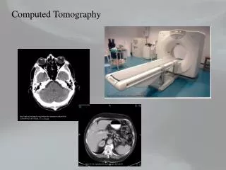
What is Emission Computed Tomography? • Definition It is a type of tomography involving radioactive emissions which requires computed tomography image reconstruction methods. • Two Types include positron emission tomography (PET) – Uses radiotracers that generate positron decay – Positron decay produces two photons in two opposite directions at a time – Use special coincidence detection circuitry to detect two photons in opposite directions simultaneously single-photon emission computed tomography (SPECT) –Use radiotracers that generate gammay decay –Capture photons in multiple directions, similar to X-ray CT – obtain projection data from multiple angles
9.1 Instrumentation9.1.1 SPECT Instrumentation • specialized ring detector systems consist of an array of individual detectors that surround the patient. Ring systems produce excellent tomograms. very expensive and relatively rare. • rotating Anger cameras mounted on a special ganrty that allows 360-degree rotation around the patient. popular.
SPECT Collimator • Collimator The collimator defines the kind of projection and determines the direction of the incident photon for any scintillation in the crystal. • The types of collimators parallel-hole, converging, diverging, and pinhole. • Two types of collimators are used in SPECT parallel-hole fan-beam(like converging collimators)
multiple Anger camera detectors • multiple Anger camera detectors(so-called heads) It is perhaps the biggest recent advance in SPECT systems because adding camera heads increases sensitivity. • Benefits provided 1. decrease noise while using the same acquisition time as with single-head system 2. decrease acquisition time to get the same counts as a single-head system 3. It may be "traded" for higher resolution through the use of higher resolution/lower sensitivity collimators
comparison between dual-head and single-head table 9.1 in p304
Picture of SPECT system it looks like a CT or MRI system but hardware is different
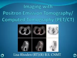
9.1.2 PET Instrumentation When a positron is emitted, it travels up to several millimeters in the tissue, depositing its kinetic energy. It then meets a free electron in the tissue, and mutual annihilation occurs. Two photons appear and are emitted back-to-back(180° apart).
It's possible to use a single-head Anger camera to individually detect one of the two 511keV gamma ray photons that are emitted by positron-electron annihilation. • But it's more advantageous to detect the two gamma rays at the same time. (Annibilation coincidence detection, ACD) • Because direction is automatically provided by 2 co-linear photons • Consequently, we do not need any collimator
Dual-head SPECT scanners can be used for PET. But because of positioning uncertainty increases when the same camera is used for lower energy SPECT and the inefficient angular acquisition, dual-head SPECT scanners are not the ideal solution for PET.
Full-fledged PET system Geometry of a multiple-ring PET system Geometry of a PET detector block
9.2 Image Formation9.2.1 SPECT Image Formation • Coordinate systems laboratory coordinate system + rotating coordinate system We use A(x,y,z) to denote the radioactivity within the 3-D body, and want A(x,y) to represent a reconstructed cross-section for a fixed z position.
Imaging Equation • where, mu is the attenuation co-efficient
Reconstruction The convolution back-projection formula for SPECT is given by is an approximate ramp filter
9.2.2 PET Image Formation • Coordinate systems We consider only 2-D PET for ease of understanding, the reconstruction of axial cross-section from data collected within isolated axial detector rings. Integration geometry for PET imaging equation
9.2.3 Iterative Reconstruction • Basic concept The reconstruction of an image from the acquired data is an inverse problem. Often, it is not possible to exactly solve the inverse problem directly. In this case, a direct algorithm has to approximate the solution, which might cause visible reconstruction artifacts in the image. Iterative algorithms approach the correct solution using multiple iteration steps, which allows to obtain a better reconstruction at the cost of a higher computation time.
9.3 Image Quality in SPECT and PET9.3.1 Spatial Resolution • Definition - Spatial resolution in PET and SPECT derive from the desire to specify that distance by which two objects must be separated to perceive them as discrete. - In an ideal detection device, an infinitely small isotopic source might be rendered graphically as a vertical line whose infinitely narrow width reflected perfect spatial resolution. - When viewed in an actual PET or SPECT scanner, however, radioactivity from such a point source is spread-out and appears as a Gaussian curve. - This so-called point (or line) spread function (psf) characterizes a camera's resolving capacity AND reflects the degree of spatial diffusion of imaged radioactivity.
9.3.2 Attenuation and Scatter • Attenuation A significant number of high-energy g photons escape detection by PET and SPECT scanners as a result of their interactions with surrounding tissues. The physical basis for attenuation effects derives from the interaction of g rays with atomic electrons. In Compton scattering, a g photon is deflected from its original trajectory after colliding with an electron and loses a fraction of its original energy in the process. Alternatively, collision may instead result in the complete absorption of a photon's energy. In the latter instance, the imparted kinetic energy is generally sufficient to eject the electron from the atom, and thus g radiation is said to be ionizing. Photon attenuation is less problematic for PET than for SPECT. Since photons in PET have higher energies
Scatter Accurate reconstruction in PET and SPECT depends on the detection of high-energy photons that travel in a straight path. However, Compton effects cause photons to deviate from their original trajectories. Since many scattered photons retain a sufficient degree of energy to escape from the body, the detection of scattered events leads to the misinterpretation of photon trajectories and produces errors in image reconstruction. The net effect of such errors is similar to that of accidental coincidences, namely an increase in background noise that compromises image contrast.
Random Coincidences These occur when one annihilation photon from one electron-positron annihilation event, and another annihilation photon from a different electron-positron annihilation event are detected in coincidence. random coincidence count rate: where is the coincidence time window width and S+ and S- are the individual count rates of opposing detectors.
Contrast differences between the image intensity of an object and surrounding objects or background. • In SPECT and PET, fmax and fmin are from reconstructed images • Noise and signal-to-noise Noise arises from: (1) the random statistical nature of radioactive decay, as well as (2) potentially from the imaging hardware and (3) certain image processing operations, and influences the "noise" component of the ratio.
That's all • Thanks • References - Medical Imaging Signals and Systems, chapter 9. - Web,Yao Wang, Medical Imaging, chapter 8,9. - Robert T. Malison, Marc Laruelle, and Robert B. Innis Positron and Single Photon Emission Tomography