Installation
Installation. Installation. Installation Process. Site Survey and Preparation. Base Station Installation. Subscriber Unit Installation. LOS Evaluation Site Evaluation Radio Survey. Access Unit Outdoor Unit Installation. Subscriber Unit Outdoor Unit Installation. Base Station

Installation
E N D
Presentation Transcript
Installation Installation Process Site Survey and Preparation Base Station Installation Subscriber Unit Installation LOS Evaluation Site Evaluation Radio Survey Access Unit Outdoor Unit Installation Subscriber Unit Outdoor Unit Installation Base Station Indoor Unit Installation Subscriber Unit Indoor Unit Installation Site Preparation
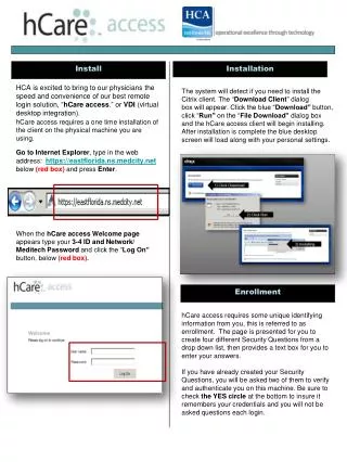
Installation Safety and Installation Considerations Installation Consideration • The indoor units must be connected directly to the DC Supply System grounding electrode conductor • All indoor equipment in the immediate vicinity must be grounded in the same way, and not be grounded elsewhere • The DC supply system is to be local, i.e. within the same premises as the indoor equipment • There shall be no disconnect device between the grounded circuit conductor of the DC source (return) and the point of connection of the grounding electrode conductor • Ensure that outdoor units, antennas and supporting structures are properly installed to eliminate any physical hazard to either people or property • Verify that the installation of the outdoor unit, antenna and cables is performed in accordance with all relevant national and local building and safety codes • Even where grounding is not mandatory according to applicable regulation and national codes, it is highly recommended to ensure that the outdoor unit and the antenna pole (when using external antenna) are grounded and suitable lightning protection devices are used so as to provide protection against voltage surges and static charges • In any event, Alvarion is not liable for any injury, damage or regulation violations associated with or caused by installation, grounding or lightning protection
Installation Safety and Installation Considerations Electronic Static Discharge (ESD) • The Base Station includes devices that can be damaged by accidental introduction of ground or foreign voltages etc • An electrostatic discharge on a component at a voltage exceeding 600 volt is sufficient to damage the component, even if mounted on a board • WARNINGDue to ESD, Electronic boards must be stored in anti-static envelopes or inside packages, during transportation and storageIt is recommended an anti-static bracelet connected to ground via protective resistance to avoid circuits damage when handling printed circuits • All electronic components are subject to ESD electrostatic discharges • Electrostatic discharges at voltage ratings below 4000 volts are not normally detected or perceived in any other form by the persons causing the actual discharges • For example, the natural movements of a person wearing synthetic clothing may generate electrostatic voltages exceeding 10,000 V! • Components are damaged by an electrical break in the ultra-thin insulating layer in the integrated circuits (measuring typically 0.0001 mm) • The damage may be serious and cause the immediate function failure or remain latent and occur later, only after a certain time span has elapsed, which could also be several years!
Installation Safety and Installation Considerations ODU Positioning • The ODU can be either pole/tower or wall mounted • Its location should enable easy access to the unit for installation and testing • Outdoor units with a connection to an external antenna should be installed as close as possible to the antenna • The antenna should be positioned in such a way that the coverage will not be affected by environmental conditions of the roof or house on which it is installed • For instructions on installing the antenna, refer to the manufacturer’s installation instructions provided with the antenna • The higher the placement of the antenna, the better the achievable link quality • The antenna of the Access Unit should be installed so as to provide coverage to all Subscriber Units within its service area • The recommended minimum distance between any two antennas is 1 meters • The antenna should be installed to provide a direct, or near line of sight with the coverage area
Installation Safety and Installation Considerations Antenna Positioning • When the BS antenna is installed outside the boundaries of the roof • The minimum distance between the antenna and the railing or building side is 25 cm • The angle between the antenna and the roof is 22 degrees • When the BS antenna is installed on a pole on top of the railingThe antenna is not blocked by anything on the roof, or on adjacent roofs • It is essential to maintain a minimum distance of 1.5m between the lower part of the antenna and the top of the roof, fence or railing, whichever is closer to the antenna • When the BS antenna is installed on a pole and the pole is installed towards the center of the roofThe antenna may be blocked by objects on the roof or by the railing or fence • It is essential to maintain a minimum distance between the lower part of the antenna and fence or railing, in order to minimize disturbance of the antenna’s lobe • The distance to the roof’s floor and the fence depends on the distance of the antenna from the railing • The farther the horizontal distance of the antenna from the raising, the larger the vertical distance
Installation Safety and Installation Considerations Heat Dissipation • Use the following formula to calculate the heat dissipation for each Base Station: • [(Module 1 power consumption) + (Module 2 power consumption) + … (Module N power consumption)] x 2.3884 = BTU • For example, for a Base Station with 1 AU and 1 NPU (and no redundancy), the heat dissipation is as follows: • [(PIU = 30 Watt) + (PSU = 200 Watt) + (NPU = 65 Watt) + (AU-IDU = 41 Watt) + (AVU = 24 Watt)] x 2.3884 = 860 BTU
Installation Installation Process Site Survey • Check whether there are line of sight conditions between the Access unit and Subscriber units Note: BreezeMax CPE can also associate in Non-LOS conditions • Estimate the distance between the AU and SUs • Map the radio interference located at the site • Validate the basic environmental conditions for the proper functioning of the BreezeMax system • Poles position • Power lines • Grounding • IF cable length • Air conditioning • etc.
Line of Sight? Installation Installation Process Site Survey - Distance and LOS Binocular
Installation Installation Process Site Survey - Radio Survey • Provide RF spectrum information of the installation site at the selected frequency range Antenna Band Pass Filter Amplifier Spectrum Analyzer
Installation Installation Process Site Preparation • Verify the following: • Safe and free of obstacle access to the Mast • Mast and ODU are properly grounded • Install antenna mast according to the site plan and site survey • Position the antenna on the mast in such a way that no one can cross the air link • Rack Preparation • Placement of the rack based on the proposed Shelf location • Preparation of the required screws • Verify existence of grounding bar • -48 VDC power supply • Cable ducting for the following: • IF cable • Power cable • Ethernet cables • Ventilation • Verify proper grounding of all indoor devices
Installation Installation Process Site Preparation • Power Distribution Lines for the Shelf • A separate circuit breaker for each PIU • Polarity check for each cable • AU IDU-ODU IF Cable • The IF cable attenuation should not be higher than 19 dB @ 240 MHz , 15 dB @ 140 MHz and 8 dB @ 64 MHz • Maximum IF cable DC Resistance 4 ohm • Double shielded cable • IF connector is TNC jack, lightning protected • In case of an external antenna installation, an additional RF cable with N-type connectors will be connected from the AU RF connector marked with to the antenna
Installation Installation Process Site Preparation • SU IDU-ODU CAT5e Cable • Indoor to outdoor Category 5 Ethernet cable with two shielded RJ-45 connectors is used in order to connect the CPE unit to the outdoor • The length of the Ethernet cable connecting the CPE to the user's equipment, together with the length of the Indoor-to-Outdoor cable, should not exceed 100 meters • In case of an external antenna installation, an additional RF cable with N-type connectors will be connected from the SU RF connector marked to the antenna • The Indoor-to-Outdoor cable provides pin-to-pin connection on both ends • All eight pins are in use • The drawing shows the wire pair connections required for the Indoor-to-Outdoor cable
Installation Installation Process Site Preparation • SU IDU-ODU CAT5e Cable • The color codes used in cables supplied by Alvarion with crimped connectors are as follows:
Installation Installation Process "H" Type Antennas Mounting Bracket • The “H” Type Antennae Mounting bracket is an “H” shaped metal bar • Up to 4 ODUs can be installed on the Base Station Tower per sector with a diversity of 1.3 m between Antennae • It is designed to be installed on different types of structures: • Monopoles • Masts • Towers ODU Lightning Rod
Installation Installation Process Types of “H” adaptors Monopole 3 sectors Mast Monopole 4 sectors Tower Leg
Installation Installation Process Types of “H” adaptors
Installation Installation Process ODU Installation • The Outdoor Unit can be mounted on a pole using one of the following options: • Special brackets and open-ended bolts are supplied with each unit. • There are Two pairs of threaded holes on the back of the unit, enabling the special brackets to be mounted on diverse pole widths • The grooves on the topsides of the unit and a protrusion on the bottom (back side) enable the use of metal bands to secure the unit to a pole Note: The bands should be 9/16" wide and at least 12" long • Installing an outdoor unit on a pole, using the brackets and open-ended bolts • Insert the open ended bolts with the grooves pointing outward, as these grooves enable you to use a screwdriver to fasten the bolts to the unit • A distance of at least 1m is required between two neighboring ODU
Installation Installation Process ODU Installation • Installing an outdoor unit on a pole, using the metal bands • Insert the bands into their designated place at the ODU (at the top and at the bottom) • Attach the bands to the pole by fastening the bands' screw • Use isolation material (such as tar bands) to cover all outdoor connectors to prevent water penetration into the cables • Using 3M's cold shrink tube 8426-9 as a solution for sealing is recommended • This solution requires no training or special tools • If you are using the 8426-9 cold shrink, leave a 10 cm space to keep the cable flexible
Installation Installation Process BS Antenna Alignment • Identify a reference point on the landscape that is in the direction of the heading of the Base antenna • Depending on whether you are looking from the left or the right side of the antenna, add or subtract 90° to/from the Base Station azimuth • Using the compass, align the outer frame of the antenna to the newly calculated azimuth, so that the flat surface of the antenna faces the reference point. This reference point is 90° to the Base antenna heading
Installation Installation Process BS Antenna Alignment - Using a Compass • When aligning the antenna on top of a tower, don't align using a compass when you are on top of the tower, due to the fact that the tower interfere with the magnetic field of the compass • True North definitionnavigational term referring to the direction of the North Pole relative to the navigator's position • Magnetic North definitionthe point where the geomagnetic field points vertically downwards, i.e. the dip is 90°, was proposed in 1600 by Sir William Gilbert, a courtier of Queen Elizabeth I • Due to the fact there is a difference between these two points, Variations is defined as the angular difference between thesetwo directions • The compass is always referring to the Magnetic north while a GPS can point either to the True north or to the magnetic north depends on the GPS type and configuration • After aligning the antenna check within 100m from the BS (in the direction of the middle of the antennabeam width) that the direction of theBS from your point is 360º - (BS antenna direction)º Magnetic North 360º - 45º = 315º SU Antenna 45º Magnetic North Antenna Direction Sector #1
Installation Installation Process Subscriber Antenna Alignment • Point the antenna towards the general direction of the Base Station • Verify that at least one LED (LED 2) of the LINK QUALITY bar display is on, indicated that the unit is synchronized with the AU • Rotate the antenna until the maximum Link Quality reading is achieved • Verify that the power indication of the unit is On
Installation Installation Process Base Station IDU Installation • Attach the cable guide to the top panel of the chassis using the screws and washers supplied with the cable guide • Install the chassis in a 19" cabinetNote: For installation in a ETSI rack a suitable adaptors should be installed on the chassis • To provide sufficient space for the cable guide and to allow air flow to prevent over-heating, leave a space of at least 1U between the upper covers of the chassis and other units in the cabinet • Connect one end of the grounding cable to the ground terminal located on the rear panel of the chassis and firmly tighten the grounding screw • Connect the opposite end of the grounding cable to a ground connection or to the cabinet, if applicable • Carefully insert the modules into the relevant slots • Secure the modules in their intended locations • Place blank covers over all of the unused slots • Connect the DATA port of the NPU to the backbone data equipment (use a straight Ethernet cable to connect to a hub/switch/router)Note: The maximum length of the Ethernet cable is 100m when operating at 100 Mbps and 70 m when operating at 1 Gbps • If the MGMT port will be used for remote management, connect it to the appropriate data equipment (use a straight Ethernet cable to connect to a hub/switch/router)Note: The maximum length of the Ethernet cable is 100 m
Installation Installation Process Base Station IDU Installation • Connect the DC power cable to the power jack of the PIU module • If a redundant PIU is installed, connect a DC power cable also to the second PIU module • Connect the power cord(s) to the -48 VDC power source(s), as follows: • Connect the black wire to the -48 VDC contact of the power source • Connect the red wire to the + (Return) contact • Connect the ground wire to the ground • Connect the IF cable(s) • To avoid transmissions at undesired frequencies, verify that the frequency and bandwidth parameters are properly configured before connecting the IF cables
Installation Installation Process Base Station IDU Installation • Each shelf contains the following equipment • BMAX-BST-SH-SP Base Station Chassis • BMAX-BST-AVU Air Ventilation Unit (installed) • BMAX-BST-PIU (1 or 2 per Base Station chassis) Power Interface Unit(s) • BMAX-BST-PSU (up to 4 per Base Station chassis) Power Supply Unit(s) • BMAX-BST-NPU Network Processing Unit • BMAX-BST-AU-IDU (up to 6 per Base Station chassis) Access Unit Indoor Unit(s) • Additional equipment and accessories • Ethernet cable (straight) for connecting the NPU to a Hub/Switch • DC power cable(s) – Shielded with 2 10AWG conductors • A ground cable with appropriate terminations for connecting the chassis to the rack • ETSI rack adaptors (if required) • Portable PC for configuring parameters using the Monitor cable
N P U A U A U A U A U A U A U A U Installation Installation Process Base Station IDU Installation Cable Tray Mounting Holes Mounting Holes • The cable tray should be installed on the top of the chassis front to enable convenient routing of cables connecting to power source(s), outdoor unit(s) and other equipment
Installation Installation Process Base Station IDU Installation • Hold the ejector levers and insert the card to its designated place in the shelf • Slide the card fully into its place • Push ejector levers in the inner direction (towards the card) • A "click" sound indicates that the ejector levers are locked and the card is fully inserted • Fasten the two (or one) captive screws of the card
Installation Installation Process Base Station Card Removal • Loosen the two (or one) captive screws of the requested card • Unlock the ejector levers by pressing the red button • Pull the ejector levers outwardly (from the card out) • Pull the card out by its ejector levers and remove it from the shelf
Installation Installation Process Subscriber Unit IDU Installation • The unit can be placed on a desktop, rack or wall-mounted • The drilling template included with the unit can be used to simplify the wall installation process • Assemble an RJ-45 connector with a protective cover on the indoor end of the IDU-ODU cable • Connect the IDU-ODU cable to the RADIO connector • Connect the power cord to the unit’s AC socket, located on the rear panel. Connect the other end of the power cord to the AC mains • Verify that the POWER LED located on the front panel is lit, indicating that the unit is supplying power to the radio port • Configure the basic parameters and align the antenna for maximum RSSI and SNR level • Connect the 10/100 Base-T ETHERNET connector to the data equipment • The cable connection should be a crossed Ethernet if connecting to a Hub/Switch and a straight cable if connecting directly to a PC Network Interface Card
Connect the Power Adapter DC cable to the POWER jack of the CPE Connect the AC power cord to the Power Adapter Connect the other end of the power cord to the AC mains Verify that the Status LED located on the top side of the unit is lit orange If a detached antenna is used Remove the cap on the top side of the unit to expose the RF connector Connect to it the RF cable supplied with the antenna Install the antenna (as described in the following slides) Connect to it the other end of the RF cable Fasten the antenna connector using the torque key which is supplied with the antenna kit Connect the 10/100 Base-T ETHERNET connector to the data equipment The cable connection should be a crossed Ethernet if connecting to a hub/switch Or Straight cable if connecting directly to a PC Network Interface Card (NIC) Verify proper operation of the Ethernet link by checking that the Ethernet Integrity Green LED is illuminating Installation Installation Process SU Si Installation
External Antenna Wall Mount With Pan Capability Indoor Installation Attach the suctions cups to the antenna Place the antenna on the glass in a way that the antenna connector is pointing downwards Attach it to the window by pressing the suction cups onto the glass Connect the antenna cable to the antenna connector Fasten the antenna connector using the torque key which is supplied with the antenna kit Rotate the antenna left or right so the domed surface of the antenna is perpendicular to the direction of the Base Station Check the Signal LEDs to ensure the antenna is aimed correctly Installation Installation Process SU Si Installation
External Antenna Wall Mount Indoor Installation Identify a suitable place ,preferably with line‑of‑sight or near line-of-sight to the Base Station Attach the antenna base bracket to the wall It is also possible to secure the base bracket to a pole using two ½” metal clamps Assemble the antenna to back plate with supplied screws and washers Fasten the back plate to the arm of base bracket Release the nut of the antenna connector (located on the bottom side of the antenna) Connect the antenna cable to the connector located on the bottom side of the antenna Installation Installation Process SU Si Installation
External Antenna Wall Mount Indoor Installation Fasten the antenna connector using the torque key which is supplied with the antenna kit Align the antenna by releasing the spike knob located next to the base bracket The bracket’s arm can be adjusted sideways or tilt up and down Position the antenna facing perpendicular to the base station cell site Tighten the spike knob to lock antenna into position Check your Signal LEDs in the SI CPE to ensure the antenna is optimally aligned If necessary, re-align antenna following steps described above Installation Installation Process SU Si Installation
Installation Installation Verification Power Up Test • After the installation process perform the following checks: • Grounding cables and connections • Power supply • Cable integrity and routing (ducting) • IF cable integrity and tightening • Antennas alignment • Shelf configuration (No of PSUs) • The power-up tests procedure assumes that the Installation procedure has been completed • These tests demonstrate that the Base Station has been correctly assembled and installed on site, all its components are functioning properly and it is now ready for commissioning • After the power-up procedure has completed successfully, the Base Station is ready for basic network definition • After power up, the Base Station automatically starts a self-testing procedure to verify that everything is working properly • During the self-test, the LEDs indicate the working status of the various components
Installation Installation Verification Power Up Test • Upon completion of the internal test and booting up (up to 5 minutes), verify that the following LEDs are lit as follows: • PIUPWR = green • If one PIU is installed, MASTER = green • If two PIU modules are installed, the MASTER LED of one PIU should be green, and the other one should be off • PSUPWR = green, ALRM = off • AVUPWR = green, ALRM = off • NPUPWR = green, ALRM = off, BST ALRM = off, Master = green • AU–IDUPWR = green, ALARM = off. ODU1 PWR = green, ODU1 ALRM = off. • If the AVU’s LED is Red, disconnect the power immediately to avoid damage to the Base Station