INSTALLATION
INSTALLATION. PURPOSE. To learn the basic steps of installing DS200 systems. INSTALLATION. Every detail about the installations of wall type systems and cabinet type systems are given in the Installation Guide. BASIC STEPS (Single rack -wall type ).


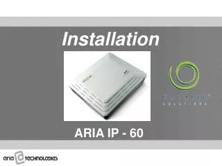
INSTALLATION
E N D
Presentation Transcript
PURPOSE To learn the basic steps of installing DS200 systems.
INSTALLATION Every detail about the installations of wall type systems and cabinet type systems are given in the Installation Guide
BASIC STEPS (Single rack-wall type) • Use the template to locate the position of the rack on the wall • Fix the rack on the wall by using the rack hanging parts • Place the cards in order • Carry the cables to the MDF • Finish the cabling
BASIC STEPS (Multiple racks) • Inter-rack backplane connections with 34-wire cables • Inter-rack power connections with 5-wire cables • Inter-rack ground connections via ground pins of racks
BASIC STEPS (Cabinet Type) • Carrying the cables to the MDF at the back of the cabinet • Locking wheels of cabinet
Aux. Rack( 6th rack ) Aux. Rack( 3rd rack ) Aux. Rack( 5th rack ) Aux. Rack( 2nd rack ) 4th Rack Main Rack( 1st rack )
BASIC STEPS (Two Cabinets) • Place the Clock Master card into the redundant CPU slot on the main rack (if no redundant CPU is available on the system) or to the second general purpose slot (if redundant CPU is available) • Connect the PCM cable to the bottom PCM connector of the main rack and the PCM connector on the Clock Master card • Connect the five PCM carrier cables to the RJ45 connectors on the Clock Master card
BASIC STEPS (Two cabinets) • Place the CCU card into the CPU slot of the 4th rack • Place the Clock Slave card into the redundant CPU slot of the 4th rack • Connect the PCM cable to the bottom PCM connector of the 4th rack and the PCM connector on the Clock Slave card • Connect the five PCM carrier cables to the RJ45 connectors on the Clock Slave card in the same order as Clock Master card • Make the power cabling by connecting the upper inter-rack SPS connector of the 3rd rack to the bottom inter-rack SPS connector of the 4th rack
CRITICAL POINTS • Grounding of the system must be very clear and effective • All the other peripherals like modems, converters, PCs, protection tools must use the same ground as the system
CRITICAL POINTS • Two step protection is recommended on MDF side • 220 VAC protection with Fuse-10 • Lightning protection with gas-discharge tubes • It is recommended to install the MDF with protection at least 20 meters away from the system in order to decrease the damage. (the cable length)
SAMPLE PROTECTION Gas discharge tubes Fuse-10 modules
CRITICAL POINTS • One block of MDF should be installed at the back side of the cabinet • Two blocks of MDF should be installed 20m (recommended) away from the system (protection elements must be used on these MDF blocks)
CRITICAL POINTS • For analog and digital interfaces 0.5 cupper wire is recommended • For E1 interfaces (PRI, R2), a shielded cable (i.e. CAT5 STP) must be used and the shield must be used to connect the ground of the system and the HDSL modem
SAMPLE E1 CABLE CAT5 STP cable Shield of the cable Twisted pairs
THANK YOU VERY MUCH... THANK YOU VERY MUCH... int.support@karel.com.tr