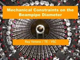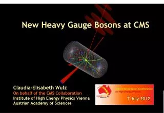
New CMS central beampipe
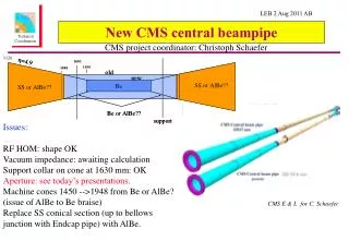
New CMS central beampipe. CMS project coordinator: Christoph Schaefer. 3120. Issues: RF HOM: shape OK Vacuum impedance: awaiting calculation Support collar on cone at 1630 mm: OK Aperture: see today’s presentations. Machine cones 1450 -->1948 from Be or AlBe? (issue of AlBe to Be braise)

New CMS central beampipe
E N D
Presentation Transcript
New CMS central beampipe CMS project coordinator: Christoph Schaefer 3120 Issues: RF HOM: shape OK Vacuum impedance: awaiting calculation Support collar on cone at 1630 mm: OK Aperture: see today’s presentations. Machine cones 1450 -->1948 from Be or AlBe? (issue of AlBe to Be braise) Replace SS conical section (up to bellows junction with Endcap pipe) with AlBe. CMS E & I, for C. Schaefer
Tolerances for aperture calculations Static, one-time & time-dependent components The possible mis-alignment of the beampipe central axis wrt the beamline has 3 classes of contributing factors: 1) static: construction tolerances and survey how well can we make the pipe and install it where it’s supposed to be with the experiment open. Basically 2s errors on nominal position. 2) one-time: displacements of the pipe from nominal caused by: - closing experiment - applying magnetic field Basically 95% CL upper limits on the displacement caused, based on observations. 3) time-dependent: ongoing distortion of the yoke (& thus movement of the pipe supports) or changes in the central wheel level wrt the beamline due to cavern floor movements. Basically 95% CL upper limits on the displacement caused, based on observations. We have added these classes linearly, which is overly conservative (but it avoids the highly complicated job of combining the values correctly!!).
Input to aperture calculations Estimated displacements, construction tolerances and survey tolerances (leading to uncertainty in distance between the beampipe wall and the beamline). Measurements/upper limits from NI mapping are likely to reduce as the technique is refined.
Low b* optics High luminosity p-p physics and HI physics are the main priorities. These must be possible for the full period between LS1 and LS 2 without significant risk of the pipe becoming an aperture limit and without any opening to correct the beampipe position. Thus the input given to Massi Giovannozzi for the n1 aperture verification is the worst case summed displacement from the LS1+3 yrs column given by summing all the contributing values in all the classes (static, one-time and time-dependent for 3 years). Our understanding is that the aperture is acceptable.
High b* optics TOTEM total cross-section measurement at 7 TeV and ~14 TeV needs high b*: - the intention is to complete these measurements as soon as possible after LS1. Difficult to foresee operating margins of machine at high b* --> Conservative solution is to stay within shadow of TAS 17± 0.1mm 17± 0.1mm (as built) Central beampipe TAS TAS rinner Implied condition rinner – summed displacement ≥ 17.1mm
High b* optics Estimates for rinner – summed displacement are time-dependent: just after LS1 ≥ 17.85mm “static” and “one-time” contributions only 1 year after LS1 ≥ 17.15mm for worst case time–development --> just OK 3 years after LS1 ≥ 15.35mm for worse case time-development --> correction needed in year-end tech stop. Machine studies will eventually determine whether a smaller aperture than this physical TAS limit is acceptable for the b*required. The actual relative alignment of beamline & beampipe will be monitored regularly by NI tomography If necessary, a correction can be made in year-end technical stop of 11-12 weeks.
Beampipe: NI radiography in z slices Maxime Gouzevitch, Guacomo Squazzoni: for TIG, May 2011 0.35mm NB allow for known tilt of Tracker frame wrt beamline!
Beamspot stability Kevin Burkett, Lenny Spiegel for TIG, May2011 Thus derive alignment of beamline wrt beampipe : 2T (2011) differs from 3.8T (2010) by only a few mm.
Conclusion Assuming agreement at LEB that aperture is OK, we would now present to LMC for Approval and proceed with the final design: Is the timescale realistic given the design issues still to be resolved? Revise? Present to LMC for approval: Aug 2011 Finalise design: Nov 2011 (EDR) is this enough?? Place order: Jan 2012 Delivery at CERN: Feb 2013 Coated and Testing complete Aug 2013 Ready for installation Dec 2013